Hi All
This is a tricky little scenario that we've been doing some circles around for a while trying to figure out a best practice practical approach.
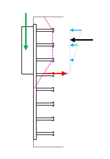
It's related to concrete breakout capacity of anchor groups in shear, particularly for shear acting towards an edge (but equally applies to shear parallel to an edge by extension), and typically for a cast in plate which might support a beam with a shear tab type connection with multiple vertical rows of anchors (3, 4, 5 rows of welded shear studs typically).
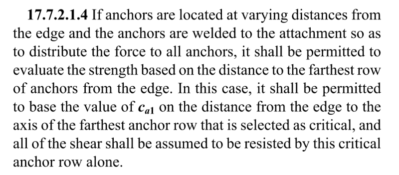
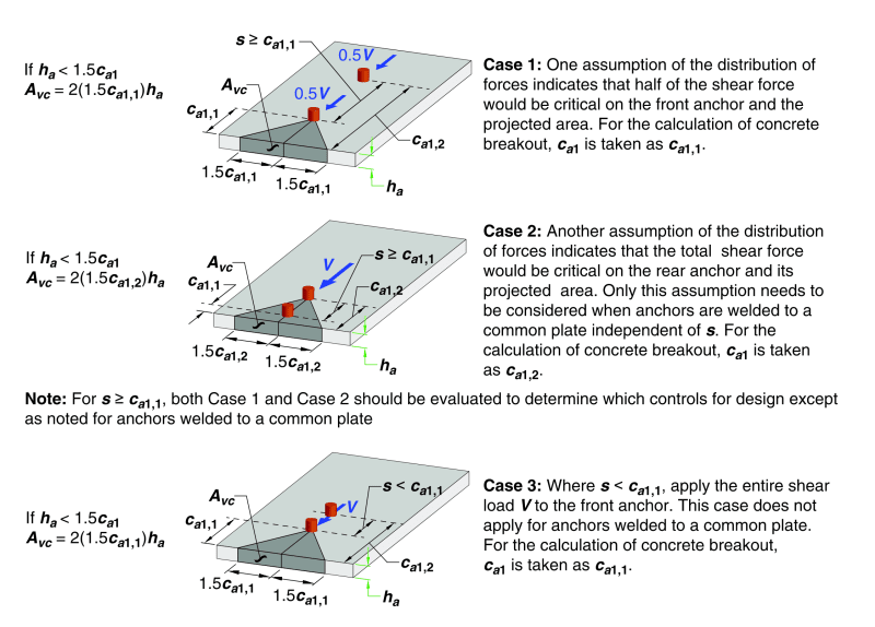
Now ACI318-19 states the following, which all makes sense for the examples given in ACI318 which include only 2 rows of anchors to keep the concepts simple (referring to the three CASES noted in the second image).
The question is how do people practically handle this?
Or what is the correct approach/interpretation when you have multiple rows of anchors (>2) in the direction of the load?
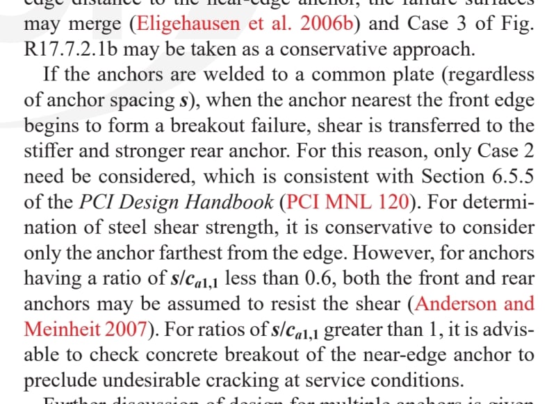
Basically if welded studs to a common cast in plate, then ACI318 is saying CASE 2 applies and you take the breakout surface on the back anchors furthest from the edge. That's all good for 2 rows like shown and makes perfect sense for that type of arrangement. The dilemma we are having is for larger plates with correspondingly larger loads if you were to perhaps take all of the shear on the back anchors, then the anchors themselves might not have sufficient strength in the steel anchor checks. This seems fundamentally an incorrect way to think of it as the other anchors in their own right might have sufficient breakout strength closer to the free edge, but the load still needs to go through the same potential breakout surface as the back studs irrespective.
Some alternative approaches we've kicked around:-
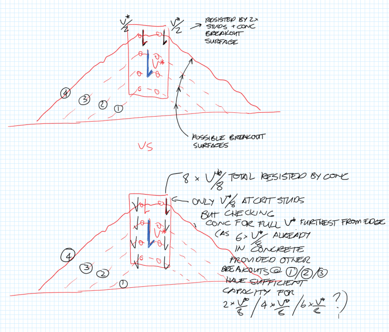
1. Check breakout assuming all anchors share a proportion of the load (neglecting any close to the edge that might fail), so the closer studs are checked progressively with their own individual breakout surface but with the accumulated load from earlier studs going through the same concrete breakout surface, but the studs them selves just see the proportion of stud shear load (shear/number effective studs) at each effective breakout surface.
2. Just adopt CASE 1 type check, checking each row individually, neglecting any rows closest to the edge that do not work for the proportion of the load (shear/number effective studs). This method seems to neglect by the time you get to rear rows that the load from the front studs is in the concrete already. But this seems to be a direct application as ACI318 spells it out, albeit we often do not comply with the spacing 's' being greater than or equal to 'c_a1' edge distance for practical connections as noted for CASE 1 (or 2 for that matter).
3. Adopt a hybrid CASE 1/2 type check, but only check the first stud closest to the edge that works for it's proportion of load, rear studs by virtue of being further from the edge imply a larger capacity and not inferred a check is necessary with CASE 1 for example (not always the case depending on how the side edges influence the breakout surface). Keep neglecting those close to the edge until you arrive at an effective number of rows that work for their proportion of the load. However, 's' is usually not going to satisfy the greater than or equal to edge distance limit.
4. Use CASE2 as stated with all the load on two rear anchors (providing some monster sized anchors at the top of the plate). This seems a bit silly, but it is a direct application of CASE 2 as stated.
I note as well in most cases your stud spacing 's' will typically be less than 'c_a1' the minimum edge distance, which only satisfies CASE 3. Which for CASE 3 states it specifically does not apply to the case of common plates! Even if it did this check is telling you to put all of the shear on the front anchors which clearly will likely result in failure if you have any decent loads and seems extremely conservative and not reflectiuve of the expectation that the shear will be distributed between the anchors furthest from the edge in some manner!
Lets ignore the fact here that you may in fact mobilise some supplementary or anchor reinforcement that is developed/provided the further from the edge you might get, and any tension that might be present. Focus the discussion on shear concrete breakout mechanism checks in isolation as that is the root of the headscatching we've got going on here in coming up with a method to generally apply to the problems like this.
Thoughts and guidance appreciated!
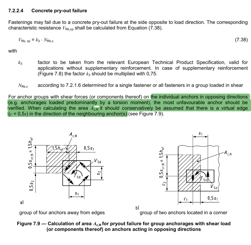
I will say as well that I have looked through a few international standards (ACI/NZ) and guidance such as the PCI Design handbook and SCI P416 and it never quite touches on this aspect. There was some discussion I found in some fib bulletins (#216) which basically had the same logic as ACI but again was only talking about 2 rows of anchors parallel to an edge.
(Let me know if the above makes no sense at all and I'll sketch something up)
This is a tricky little scenario that we've been doing some circles around for a while trying to figure out a best practice practical approach.
It's related to concrete breakout capacity of anchor groups in shear, particularly for shear acting towards an edge (but equally applies to shear parallel to an edge by extension), and typically for a cast in plate which might support a beam with a shear tab type connection with multiple vertical rows of anchors (3, 4, 5 rows of welded shear studs typically).
Now ACI318-19 states the following, which all makes sense for the examples given in ACI318 which include only 2 rows of anchors to keep the concepts simple (referring to the three CASES noted in the second image).
The question is how do people practically handle this?
Or what is the correct approach/interpretation when you have multiple rows of anchors (>2) in the direction of the load?
Basically if welded studs to a common cast in plate, then ACI318 is saying CASE 2 applies and you take the breakout surface on the back anchors furthest from the edge. That's all good for 2 rows like shown and makes perfect sense for that type of arrangement. The dilemma we are having is for larger plates with correspondingly larger loads if you were to perhaps take all of the shear on the back anchors, then the anchors themselves might not have sufficient strength in the steel anchor checks. This seems fundamentally an incorrect way to think of it as the other anchors in their own right might have sufficient breakout strength closer to the free edge, but the load still needs to go through the same potential breakout surface as the back studs irrespective.
Some alternative approaches we've kicked around:-
1. Check breakout assuming all anchors share a proportion of the load (neglecting any close to the edge that might fail), so the closer studs are checked progressively with their own individual breakout surface but with the accumulated load from earlier studs going through the same concrete breakout surface, but the studs them selves just see the proportion of stud shear load (shear/number effective studs) at each effective breakout surface.
2. Just adopt CASE 1 type check, checking each row individually, neglecting any rows closest to the edge that do not work for the proportion of the load (shear/number effective studs). This method seems to neglect by the time you get to rear rows that the load from the front studs is in the concrete already. But this seems to be a direct application as ACI318 spells it out, albeit we often do not comply with the spacing 's' being greater than or equal to 'c_a1' edge distance for practical connections as noted for CASE 1 (or 2 for that matter).
3. Adopt a hybrid CASE 1/2 type check, but only check the first stud closest to the edge that works for it's proportion of load, rear studs by virtue of being further from the edge imply a larger capacity and not inferred a check is necessary with CASE 1 for example (not always the case depending on how the side edges influence the breakout surface). Keep neglecting those close to the edge until you arrive at an effective number of rows that work for their proportion of the load. However, 's' is usually not going to satisfy the greater than or equal to edge distance limit.
4. Use CASE2 as stated with all the load on two rear anchors (providing some monster sized anchors at the top of the plate). This seems a bit silly, but it is a direct application of CASE 2 as stated.
I note as well in most cases your stud spacing 's' will typically be less than 'c_a1' the minimum edge distance, which only satisfies CASE 3. Which for CASE 3 states it specifically does not apply to the case of common plates! Even if it did this check is telling you to put all of the shear on the front anchors which clearly will likely result in failure if you have any decent loads and seems extremely conservative and not reflectiuve of the expectation that the shear will be distributed between the anchors furthest from the edge in some manner!
Lets ignore the fact here that you may in fact mobilise some supplementary or anchor reinforcement that is developed/provided the further from the edge you might get, and any tension that might be present. Focus the discussion on shear concrete breakout mechanism checks in isolation as that is the root of the headscatching we've got going on here in coming up with a method to generally apply to the problems like this.
Thoughts and guidance appreciated!
I will say as well that I have looked through a few international standards (ACI/NZ) and guidance such as the PCI Design handbook and SCI P416 and it never quite touches on this aspect. There was some discussion I found in some fib bulletins (#216) which basically had the same logic as ACI but again was only talking about 2 rows of anchors parallel to an edge.
(Let me know if the above makes no sense at all and I'll sketch something up)