Continue to Site

Eng-Tips is the largest engineering community on the Internet

Intelligent Work Forums for Engineering Professionals

  • Congratulations waross on being selected by the Eng-Tips community for having the most helpful posts in the forums last week. Way to Go!

CATIA Automation 1

Status
Not open for further replies.

catdeveloper_begin

Automotive
Sep 20, 2016
12
Hi everyone,

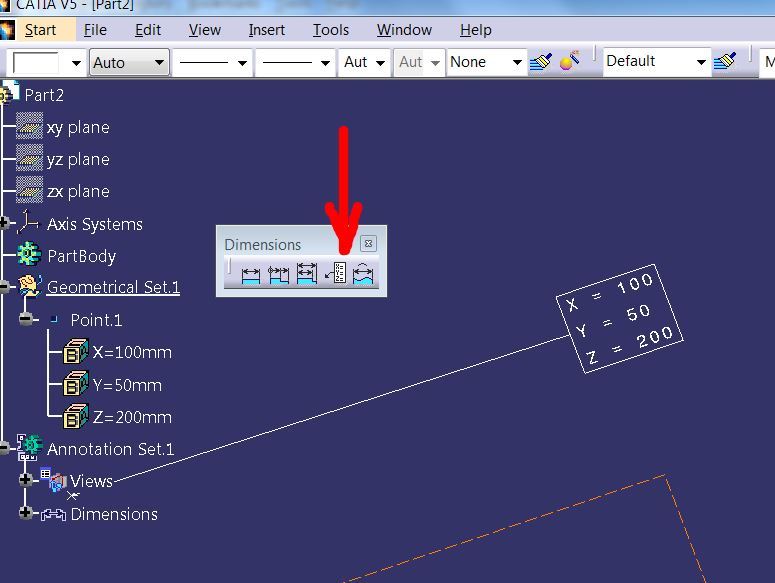
I need to automate the creation of point coordinates annotation in the FTA workbench in CATIA. As far as I have been able to find out, DS has not exposed the method for creating coordinate dimension. Is there anyway we can do it?

Attached is the screenshot for what I need
Thanks for all your help. Please let me know if you need more information.
 
 http://files.engineering.com/getfile.aspx?folder=83d8125c-1ad6-45f0-a609-179b82a1fb49&file=Point_Coord_Annotation.jpg
Replies continue below

Recommended for you

Hi

CATIA has this in R24 (for example), why you need a macro?

Capture_nbfc3x.jpg


Regards
Fernando

- Romania
- EU
 
Thanks for your reply. I know the option you are pointing out is available in CATIA. The reason I want to automate it is because I am copying a number of elements from one file to another. when these elements are copied, they need to be annotated with the coordinates of the points. this is a new process we are implementing and the designer will not have enough time to annotate the points manually. so we are creating a utility that let's the designer do it at the click of a button.
 
in this case you need to give a little bit more details about your process...but you said that DS has not exposed the method for creating coordinate dimension. You mean in FTA, isn't it? But what if you get coordinates of the points as usual and write their values as text in FTA?

Regards
Fernando

- Romania
- EU
 
yes Ferdo we tried that. We measured the coordinates of the point and entered them as a text string. However, here the problem is that the new annotation is no longer associative. that is, it does not change with the change in the location of the points and we have to re-run the code once again to re-create the annotation for it. How can we achieve the solution here?
 
So you copy the points in and can later change the coordinates of the points that were copied in?

If you want the annotation to update you need to make length parameters that are tied to the coordinates of the points, then attribute link those parameters to your annotation.

You can create three length parameters (X,Y,Z) using the .CreateDimension method
You need to create a formula to tie the point coordinates to the three parameters using the .Relations.CreateFormula method and KWE "Point->coord(rank)" (where rank = 1 for x, 2 for y and 3 for z) for the formula.

Once you have the parameters associated to the point coordinates you can attribute link the text using the .InsertVariable method.
 
Thanks lardman363 for the idea. Though I am not sure how well it will work for us.

Let me try and describe in more detail the scenario here:
1. A part, let's say A, is created by the designer.
2. A derivative part from the part A is created by publishing the part body and copying it with the "As Result With Link" option in paste special command into another part, say B.
3. Another person uses part B to design some points and patches as per his requirement inside a single geometrical set. At the end of his work, he publishes all the elements he has created.
4. These published parts are then copied back to the part A in the same way, i.e., "As Result With Link"
5. Now in part A, we need to annotate the points with the coordinate dimensions of the copied points. This is where we are stuck at now. Creating the annotations the first time is easy. It is updating them is the difficulty. Maybe I should mention here that the points are created on surface based on the requirement and not as coordinate points.

I will give the idea a try and see what happens. In the meanwhile any more help would be greatly appreciated.

Cheers!!!
 
If you reference part A into part B, you cannot reference points from part B back into part A...that creates a circular reference...so I am a bit confused on that.

But regardless of that issue...
If you want the annotation to update, you need to have parameters for the XYZ coordinates and attribute link them to the annotation.

To do this in a macro you need to do what I suggested above.

 
Here's what I got, worked well.

Code:
'Paste into Visual Basic
'Open a part
'Second geoset in the Part must contain the points (you can change this)
'Run the macro
'Macro will:
'  -Loop through all points
'  -Create XYZ parameters under the point
'  -Create a formula for XYZ parameters so they equal the location
'  -Create an annotation set and view parallel to the ZX plane (you can change this)
'  -Create annotations for the coordinates
'If you move a point on surface, the annotation updates to the new point coordinates
'*If you run it twice it will put more parameters under the points
'*Had to comment out setting oPartProduct because an open part doesn't have an associated product...but it ran fine
Sub CATMain()
	'Part declarations
	Dim oPart As Part
	Dim oPartDocument As PartDocument
	Dim oPartProduct As Product
	Dim oSelection As Selection
	Dim oRelations As Relations
	Dim oParameters As Parameters
	Dim oOriginElements As OriginElements
	Dim oXYPlane
	Dim oYZPlane
	Dim oZXPlane
	Dim oGeoset As HybridBody
	
	'Point declarations
	Dim oPoint As Point
	Dim oPointParameters As Parameters
	Dim xParam As Length
	Dim yParam As Length
	Dim zParam As Length
	Dim xFormula As Formula
	Dim yFormula As Formula
	Dim zFormula As Formula
	
	'Annotation declarations
	Dim oText As DrawingText
	Dim oUserSurfaces As UserSurfaces

	'Set part variables
	Set oPart = CATIA.ActiveDocument.Part
	Set oPartDocument = oPart.Parent
	'Set oPartProduct = oPartDocument.Product
	Set oSelection = oPartDocument.Selection
	Set oRelations = oPart.Relations
	Set oParameters = oPart.Parameters
	Set oOriginElements = oPart.OriginElements
	Set oXYPlane = oOriginElements.PlaneXY
	Set oYZPlane = oOriginElements.PlaneYZ
	Set oZXPlane = oOriginElements.PlaneZX
	Set oGeoset = oPart.HybridBodies.Item(2)'Change number to match the location of your geoset
	Set oUserSurfaces = oPart.UserSurfaces

	'make an annotation set If there isn't one
	Set oAnnotationSets = oPart.AnnotationSets
	
	If oAnnotationSets.Count = 1 Then
		Set oAnnotationSet = oAnnotationSets.Item(1)
	Else
		Set oAnnotationSet = oAnnotationSets.AddInAProduct(oPartProduct, "1")
		oPart.UpdateObject oAnnotationSet
	End If
	
	Set oAnnotationFactory = oAnnotationSet.AnnotationFactory

	'Create annotation View
	oSelection.Clear
	oSelection.Add oZXPlane 'Change the plane that is selected to put annotations on a different plane
	CATIA.StartCommand "Front View"
	Set oView = oAnnotationSet.TPSViews.Item(oAnnotationSet.TPSViews.Count)
	oSelection.Clear
	oView.Name = "View for point coordinates"
	'Hide the annotation view frame
	oPart.UpdateObject oAnnotationSet
	oSelection.Clear
	oSelection.Add oView
	oSelection.VisProperties.SetShow catVisPropertyNoShowAttr
	oSelection.Clear

	'Loop through the points in the geoset
	For I = 1 To oGeoset.HybridShapes.Count
		'Get a point in the geoset
		Set oPoint = oGeoset.HybridShapes.Item(I)
		
		'Make XYZ parameters for point, under the point
		oSelection.Clear
		oSelection.Add oPoint
		Set oPointParameters = oParameters.SubList(oPoint, True)
		Set xParam = oPointParameters.CreateDimension("xCoord", "LENGTH", 0)
		Set yParam = oPointParameters.CreateDimension("yCoord", "LENGTH", 0)
		Set zParam = oPointParameters.CreateDimension("zCoord", "LENGTH", 0)
		oSelection.Clear
		
		'Make formulas so the parameters update when the point is moved
		Set xFormula = oRelations.CreateFormula("xCoordRel", "", xParam, oPart.Parameters.GetNameToUseInRelation(oPoint) & "->coord(1)")
		Set yFormula = oRelations.CreateFormula("yCoordRel", "", yParam, oPart.Parameters.GetNameToUseInRelation(oPoint) & "->coord(2)")
		Set zFormula = oRelations.CreateFormula("zCoordRel", "", zParam, oPart.Parameters.GetNameToUseInRelation(oPoint) & "->coord(3)")
		
		'Create dummy annotation
		Set oRefPoint = oPart.CreateReferenceFromObject(oPoint)
		Set oUserSurface = oUserSurfaces.Generate(oRefPoint)
		Set oAnnotation = oAnnotationFactory.CreateEvoluateText(oUserSurface, 10, 10, 10, True)
		oAnnotation.Text.Text = "X=a" & vbCrLf & "Y=b" & vbCrLf & "Z=c"
		
		'Attribute link dummy annotation
		Set oText = oAnnotation.Text.Get2dAnnot
		oText.InsertVariable 11, 1, xParam
		oText.InsertVariable 7, 1, yParam
		oText.InsertVariable 3, 1, zParam
		oText.ActivateFrame catRectangle
		
	Next
	
	oPart.UpdateObject oAnnotationSet
	
End Sub
 
Status
Not open for further replies.

Part and Inventory Search

Sponsor