Continue to Site

Eng-Tips is the largest engineering community on the Internet

Intelligent Work Forums for Engineering Professionals

  • Congratulations waross on being selected by the Eng-Tips community for having the most helpful posts in the forums last week. Way to Go!

[CATIAV5] LF VBA Macro to generate normal axis systems on projected points.

Status
Not open for further replies.

DSESDJ

Aerospace
May 14, 2024
5
Hello all,


Unfortunately my VBA knowledge is limited, especially related to Catia therefore I'm looking for some help in creating a VBA macro for Catia V5.
I'll describe what the macro I have envisioned does:

1. The macro prompts to select a sketch, or geometric set, in which this sketch is located.
2. The macro generates outputs features of all points in this sketch. It also counts the amount of points.
Something like:

CATIA.ActiveDocument.Selection.Search "CATGmoSearch.Point,sel"
Dim objSelection As Selection
Set objSelection = CATIA.ActiveDocument.Selection.

3. The output points are projected on a surface. Maybe select this surface in earlier stage when prompted to select sketch or geometrical set.

For loop i=1 to objSelection.Count 'iteration over all projected points.
4. Construct a line.(i) through projection point(i), normal to the surface it has been projected on.
5. Create an Axis system.(i), with the origin projection point(i) and z axis direction of line.(i)
Next

Anyone already have a macro that's similar, or is versed in translating above logic into actual code?


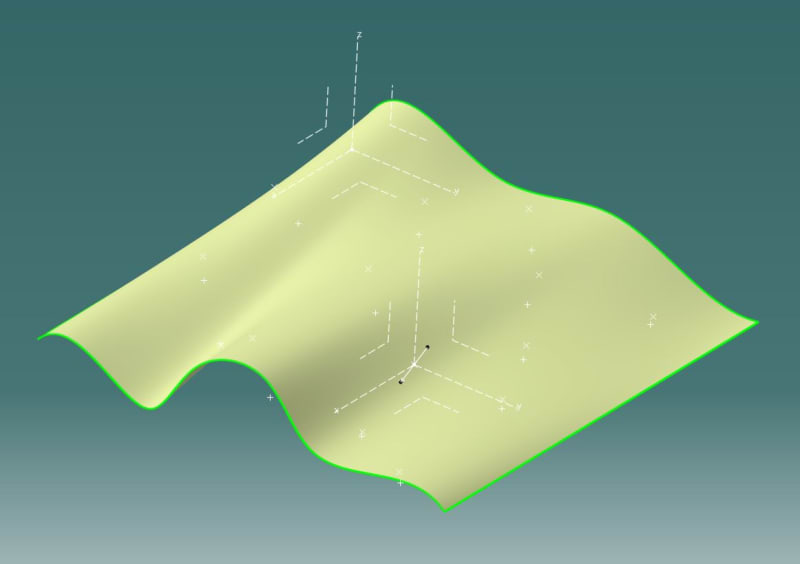
In this image I made 1 axis system on Blend.1 at projection.2 using line.2
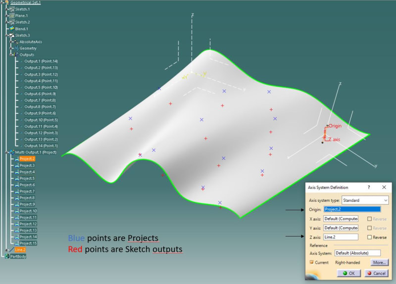
Macro_dmxgjd.jpg

Recorded code:

Code:
Language="VBSCRIPT"

Sub CATMain()

Set partDocument1 = CATIA.ActiveDocument

Set part1 = partDocument1.Part

Set hybridShapeFactory1 = part1.HybridShapeFactory

Set hybridBodies1 = part1.HybridBodies

Set hybridBody1 = hybridBodies1.Item("Geometrical Set.1")

Set hybridShapes1 = hybridBody1.HybridShapes

Set hybridShapeBlend1 = hybridShapes1.Item("Blend.1")

Set reference1 = part1.CreateReferenceFromObject(hybridShapeBlend1)

Set hybridBodies2 = hybridBody1.HybridBodies

Set hybridBody2 = hybridBodies2.Item("Multi Output.1 (Project)")

Set hybridShapes2 = hybridBody2.HybridShapes

Set hybridShapeProject1 = hybridShapes2.Item("Project.2")

Set reference2 = part1.CreateReferenceFromObject(hybridShapeProject1)

Set hybridShapeLineNormal1 = hybridShapeFactory1.AddNewLineNormal(reference1, reference2, -20.000000, 20.000000, False)

hybridBody1.AppendHybridShape hybridShapeLineNormal1

part1.InWorkObject = hybridShapeLineNormal1

part1.Update 

Set axisSystems1 = part1.AxisSystems

Set axisSystem1 = axisSystems1.Add()

axisSystem1.OriginType = catAxisSystemOriginByPoint

Set reference3 = part1.CreateReferenceFromObject(hybridShapeProject1)

axisSystem1.OriginPoint = reference3

axisSystem1.XAxisType = catAxisSystemAxisByCoordinates

Dim arrayOfVariantOfDouble1(2)
arrayOfVariantOfDouble1(0) = 0.999990
arrayOfVariantOfDouble1(1) = 0.004416
arrayOfVariantOfDouble1(2) = 0.000000
axisSystem1.PutXAxis arrayOfVariantOfDouble1

axisSystem1.YAxisType = catAxisSystemAxisByCoordinates

Dim arrayOfVariantOfDouble2(2)
arrayOfVariantOfDouble2(0) = -0.004246
arrayOfVariantOfDouble2(1) = 0.961457
arrayOfVariantOfDouble2(2) = -0.274924
axisSystem1.PutYAxis arrayOfVariantOfDouble2

axisSystem1.ZAxisType = catAxisSystemAxisSameDirection

Set reference4 = part1.CreateReferenceFromObject(hybridShapeLineNormal1)

axisSystem1.ZAxisDirection = reference4

part1.UpdateObject axisSystem1

axisSystem1.IsCurrent = True

part1.Update 

Set settingControllers1 = CATIA.SettingControllers

Set visualizationSettingAtt1 = settingControllers1.Item("CATVizVisualizationSettingCtrl")

visualizationSettingAtt1.SaveRepository 

End Sub

Unfortunately this recorded macro works only for this exact coordinates and I need something thats linked to the inputs.


Thanks for reading,

Kind regards,

Sander.
 
Replies continue below

Recommended for you

Code:
Sub CATMain()

    'DESCRIPTION: Function to create normal lines to a surface
    'INPUT: Select a group of projected points, and the surface.
    'OUTPUT: Creates a normal line for each of the projected points.

    Dim uPart As Part
    Set uPart = CATIA.ActiveDocument.Part
    
    Dim HSF As HybridShapeFactory
    Set HSF = uPart.HybridShapeFactory
    
    Dim uSel As Selection
    Set uSel = CATIA.ActiveDocument.Selection
    
    Dim ProjectBody As HybridBody
    Set ProjectBody = uSel.Item(1).Value
    
    Dim NormSurfaceRef As Reference
    Set NormSurfaceRef = uSel.Item(2).Value
    
    Dim InputSet As HybridBody
    Set InputSet = ProjectBody.Parent
    
    Dim inProj As HybridShapeProject
    For Each inProj In ProjectBody.HybridShapes
        Dim PntRef As Reference
        Set PntRef = uPart.CreateReferenceFromObject(inProj)
        
        Dim NormLine As HybridShapeLineNormal
        Set NormLine = HSF.AddNewLineNormal(NormSurfaceRef, PntRef, -25.4, 25.4, True)
        
        InputSet.AppendHybridShape NormLine
        uPart.UpdateObject NormLine
    Next

End Sub
 
Hello weagan22,


Thanks for the reply. Looks like this script is supposed to make normal to surface lines through projected points, a good start.

When i try this script however I get a runtime error at this line:
Code:
    Set ProjectBody = uSel.Item(1).Value

In the supplied part I selected Blend.1 (the surface) and Project.1 (the projected points on this surface)

I've tried with a projection of a sketch with multiple points.
I've tried with a multi projection of normal points (Generative Shape Design)
I've tried with multiple single projections of normal points (Generative Shape Design)
I've tried with setting Tools>Options>Infrastructure>Part Infrastructure>Part Document>Hybrid design> Enable hybrid design inside part bodies and bodies on Checked and Unchecked.

Everytime it fails at that line of code. Im in Catia V5R32, what am I doing wrong?
Did you get it to work on the supplied CATPart?


Kind regards,

Sander
 
You have to select in the correct order. First select the group Multi Output.1 (Project), then the surface Blend.1. It is looking for the first selected item to be a HybridBody.
 
Thanks Weagan22,


It got it to work, but I have to run it twice from the VBA Debugger:

Select Multi Output.1 (Project)
Select Blend.1
Alt+F8 > Run Macro

Unfortunately this does nothing.

When I go to Macros > Edit
Then run the macro there twice, with F5 or play button. Then it works, which I find kind of odd.

I'll try to build onward from this one and try to make the desired axis systems.

Thanks for the help sofar!
 
Good Monday,


I got the macro to work up to the point it creates the Axis systems and links the Z axis to the generated normal lines.
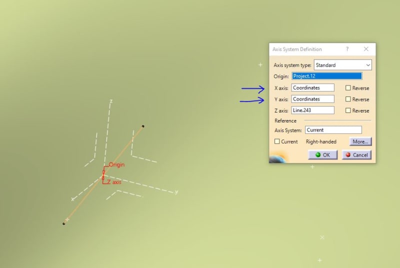
However CATIA generates some coordinate inputs for the X and Y direction.
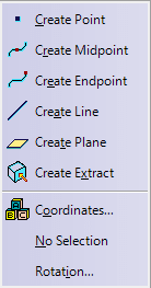
I've searched the internet for documentation how I can clear this selection, unfortunately I have not found the answer.
Anyone know if this is possible?
(Screenshots and code below)

ASDF1_y44asr.jpg

Fig.1 - Generated output on one projected point.

ASDF2_kib7uf.jpg

Fig.2 - Closeup.

ASDF4_po0dlq.png

Fig.3 - Dropdown box, to select No Selection

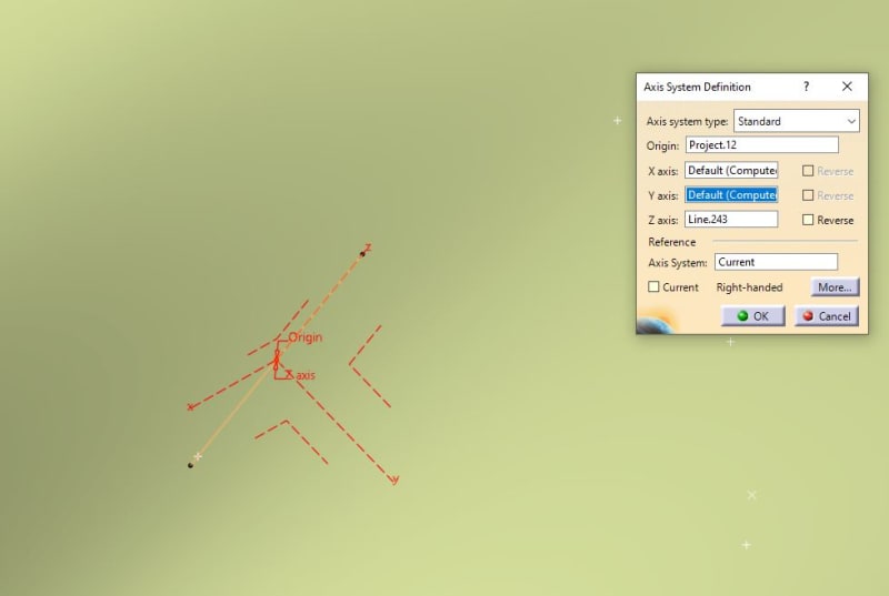
ASDF3_zkvume.jpg

Fig.4 - Desired output.


Code:
Sub CATMain()

    'DESCRIPTION: Function to create normal lines to a surface
    'INPUT: Select a group of projected points, and the surface.
    'OUTPUT: Creates a normal line for each of the projected points.

    Dim uPart As Part
    Set uPart = CATIA.ActiveDocument.Part
    
    Dim HSF As HybridShapeFactory
    Set HSF = uPart.HybridShapeFactory
    
    Dim uSel As Selection
    Set uSel = CATIA.ActiveDocument.Selection
    
    'selection 1 - multi project points'
    Dim ProjectBody As HybridBody
    Set ProjectBody = uSel.Item(1).Value
    
    'selection 2 - project surface'
    Dim NormSurfaceRef As Reference
    Set NormSurfaceRef = uSel.Item(2).Value
    
    Dim InputSet As HybridBody
    Set InputSet = ProjectBody.Parent
  

    Dim inProj As HybridShapeProject
    For Each inProj In ProjectBody.HybridShapes
        'Set projection points as reference'
        Dim PntRef As Reference
        Set PntRef = uPart.CreateReferenceFromObject(inProj)
        'Generate Normal Lines'
        Dim NormLine As HybridShapeLineNormal
        Set NormLine = HSF.AddNewLineNormal(NormSurfaceRef, PntRef, -25.4, 25.4, True)
        InputSet.AppendHybridShape NormLine
        uPart.UpdateObject NormLine
        'Generate axis sytstems'
        Dim AxSys As AxisSystem
        Set AxSys = uPart.AxisSystems.Add()
        AxSys.OriginType = catAxisSystemOriginByPoint
        AxSys.OriginPoint = PntRef
        AxSys.ZAxisType = catAxisSystemAxisSameDirection
        AxSys.ZAxisDirection = uPart.CreateReferenceFromObject(NormLine)
       
    Next
    
End Sub

Thanks for reading and kind regards,

Sander
 
can you try to add
axisSystem.XAxisType = 0
axisSystem.YAxisType = 0


Eric N.
indocti discant et ament meminisse periti
 
Legend,

This worked!

You live up to your name!

Also thanks to weagan22 for all the great assistance!

Final Code:

Code:
Sub CATMain()

    'DESCRIPTION: Function to create normal to surface Axis systems located at projection points.
    'INPUT: Select a group of projected points, and the surface.
    'OUTPUT: Axis systems normal to surface at projection points.

    Dim uPart As Part
    Set uPart = CATIA.ActiveDocument.Part
    
    Dim HSF As HybridShapeFactory
    Set HSF = uPart.HybridShapeFactory
    
    Dim uSel As Selection
    Set uSel = CATIA.ActiveDocument.Selection
    
    'selection 1 - multi project points'
    Dim ProjectBody As HybridBody
    Set ProjectBody = uSel.Item(1).Value
    
    'selection 2 - project surface'
    Dim NormSurfaceRef As Reference
    Set NormSurfaceRef = uSel.Item(2).Value
    
    Dim InputSet As HybridBody
    Set InputSet = ProjectBody.Parent

      
    Dim inProj As HybridShapeProject
    For Each inProj In ProjectBody.HybridShapes
    
        'Set projection points as reference'
        Dim PntRef As Reference
        Set PntRef = uPart.CreateReferenceFromObject(inProj)
        
        'Generate Normal Lines'
        Dim NormLine As HybridShapeLineNormal
        Set NormLine = HSF.AddNewLineNormal(NormSurfaceRef, PntRef, -25.4, 25.4, True)
        InputSet.AppendHybridShape NormLine
        uPart.UpdateObject NormLine
        
        'Generate axis sytstems'
        Dim AxSys As AxisSystem
        Set AxSys = uPart.AxisSystems.Add()
        AxSys.OriginType = catAxisSystemOriginByPoint
        AxSys.OriginPoint = PntRef
        AxSys.ZAxisType = catAxisSystemAxisSameDirection
        AxSys.ZAxisDirection = uPart.CreateReferenceFromObject(NormLine)
        
        'Set No Selection - Default(Computed) on X and Y axis'
        AxSys.XAxisType = 0
        AxSys.YAxisType = 0
        uPart.UpdateObject AxSys
       
    Next
    
End Sub

Result:

ASDF5_brt7o5.jpg


Cheers,

Sander.
 
Hello everyone!

I've saved this code because it's useful for my works also.
I sketched a quick test part to examine it, however I have an error code at line 38:
InputSet.AppendHybridShape NormLine

I have currently hybrid design enabled if it matters (we're prohibited to use it though). I'm on R29 at the moment but have later versions.

Any guess on why it has a problem? I selected multi output first then extrude, and ran the macro.

curvepointsaxis_vlppvm.jpg
 
glad i could help....

Eric N.
indocti discant et ament meminisse periti
 
Status
Not open for further replies.

Part and Inventory Search

Sponsor