Eng-Tips is the largest engineering community on the Internet

Intelligent Work Forums for Engineering Professionals

causes for cracking at embed plate 4

Status
Not open for further replies.

struct_eeyore

Structural
Feb 21, 2017
249
0
0
US
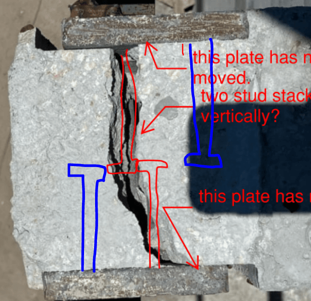
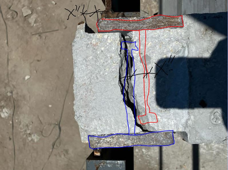
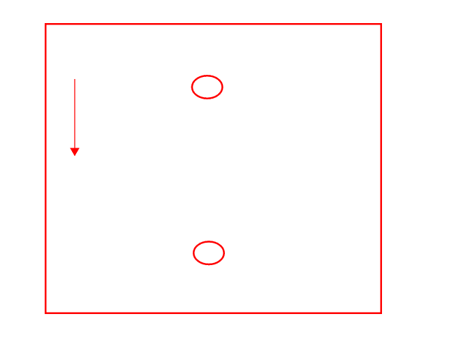
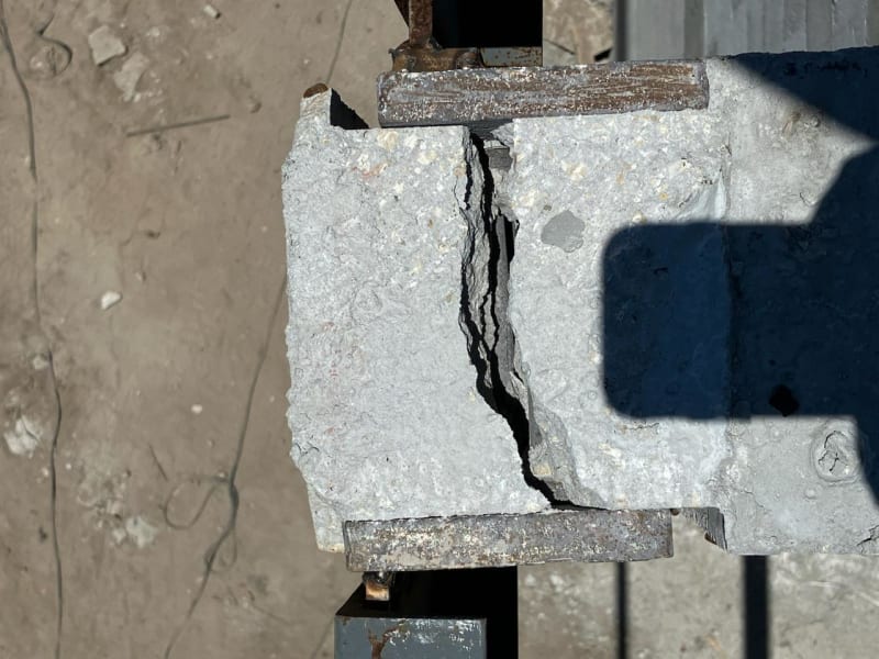
I have 2 small embed plates, 5x8x1/2 w/ 2 closely spaced headed studs at the end of a stub concrete cantilever. The embeds a staggered to fit roughly opp. of each other. The entire load carried by these two plates is about 600lb when the small section of roof they carry is fully loaded, otherwise it only supports about 250 lb. This is still in construction, and I got some lovely photos earlier today with a big old crack right down the centerline of the headed studs (see image)

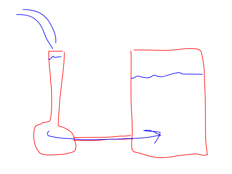
Let's for a second ignore that the top reinforcing was not installed and hooked to contain everything. Then, even with the eccentrically loaded condition, my truncated prism failure is on an order of magnitude higher than the demand, as is the plain concrete moment capacity and shear accounting for the reduction in cross section where the studs are located. So I'm really struggling to determine the cause of failure here. From one side, a 20'L channel frames in, from the other a 7' channel - could this be driven by thermal expansion? I've yet to go to the site, but it looks like there's an angle between the south beam and the embed - prying action maybe?

Open to any and all feedback.


crack_gdhcen.jpg
 
Replies continue below

Recommended for you

gte447f said:
Kootk, I believe the gaps b/t the steel plates and the concrete are explained by the fact that one of the plates (the one on the bottom of the photo) has moved with the broken off end of the concrete and the other plate (the one at the top of the photos) has stayed with the rest of the beam, right?

Right. We're on the same page there. But that's why I've been confused about the stud locations. OP confirmed the studs shown in red below but, based on the movement pattern of the plates, I feel that the studs would pretty much have to be placed as shown in blue below.

C01_cjnaxh.png
C01_cjnaxh.png
 
I assumed that the studs were offset vertically, such that in the plan view of the "as designed" condition, you`d only really see one stud.
The studs are 6" long, concrete is 8" wide, and plates are 1/2" thick. That means each stud will have 1" clear cover to the inside face of the opposite plate.
sketch_ckrah1.jpg
 
Once2006 said:
I assumed that the studs were offset vertically, such that in the plan view of the "as designed" condition, you`d only really see one stud.

That would make a lot of sense. I was having a hard time imagining embeds with asymmetric stud layouts.
 
@ Once and Koot -

The plates are in fact identical (and symmetrical) and offset horizontally. This was originally necessary for the T&B rebar to pass while maintaining cover. In case I didn't mention, there are two very closely spaced studs (aligned on the vertical CL, to develop the incidental moment couple. And again, the studs were designed to be confined on all sides before the rebar "disappeard" in the field. And forgive me if I'm repeating myself here, but even with the rebar not in place, any shear, breakout, or flexural stresses are still so low, especially from being loaded only by a 20' 13lb/ft beam, that I'm scratching my head a bit. In terms of thermal expansion from welding - the 5/8" plate should have readily eaten up most of the excess heat. My only thought now is that the beam was installed in the daytime in 100+ degree heat, and then it rained in the afternoon (Florida), and caused massive shrinkage.
 
structee said:
flexural stresses are still so low, especially from being loaded only by a 20' 13lb/ft beam, that I'm scratching my head a bit.

You have a whole lot of non-concrete 'stuff' packed into a really small area and no rebar to reinforce it. You don't need an extreme temperature cycle or uncontrolled curing to cause this. There is likely a plane that can be drawn from top of concrete to stud to stud to stud to stud to bottom of concrete that involves...well, not much concrete. So normal curing would likely cause enough stress to develop a crack here. Once that crack forms, with no reinforcement, it doesn't matter what the calculated stresses are. Any stress will exceed the capacity at the crack, which is about 0psi, and cause it to open up even more.
 
I agree with what phamENG has said above, only that I am still wondering what can cause the approximately 1/2" of horizontal movement that appears to have occurred along the axis of the concrete beam and perpendicular to the steel channel beams. I still wonder if something didn't impact one of the steel channel beams that frame into the plates, maybe even after the crack occurred.
 
Or was the shoring/support not holding this in place and there was a twisting load on it while it was trying to cure?
Some force was pushing the plates in opposite directions.
How far back will they need to demo to re-do this?

= = = = = = = = = = = = = = = = = = = =
P.E. Metallurgy, consulting work welcomed
 
OP said:
In terms of thermal expansion from welding - the 5/8" plate should have readily eaten up most of the excess heat.

I don't agree. If the welding was done properly -- and at this point that's a big if -- the larger piece of steel would require more input heat in order to achieve proper fusion. So you just wind up with a larger piece of steel that's even more impossible to restrain.
 
gte447f said:
...only that I am still wondering what can cause the approximately 1/2" of horizontal movement that appears to have occurred along the axis of the concrete beam and perpendicular to the steel channel beams.

Were I to attempt to tell the complete story of this, it would be as follows with reference to the photo below:

1) Sure, the stud congestion created a natural plane of weakness where one would expect cracking to occur should there be a longitudinal tension demand induced in the unreinforced beam.

2) The lower embed was welded successfully, without cracking the beam. The thermal expansion of this embed was not enough to crack the beam longitudinally but, perhaps, may not have been allowed to dissipate prior to welding the other embed.

3) The upper embed was welded and the thermal expansion induced in that embed initiated the crack which then spread to the other side, pushing the tip of the concrete beam off longitudinally a small amount.

4) With a full section tension crack in play, the small amount of load added to the cantilever tip pried the crack open to the width that we see in the photos. The top of the crack looks a whole lot wider than the bottom. Whatever was required to bring the situation back into equilibrium. This is the "just fell apart" component of my story.

In this rendition, a lot of the suggested causes play a role. And that's often how things go in my experience.


Koot - I admit to my own detriment I'm not a metallurgy guy, just seeking explanations. We're only welding a short shear tab to the edge of a 5/8" plate. Whatever pre-heat might have been needed, would have been limited to a very small strip, so while overall heat input might have been higher than with a thinner plate, the mass of the plate would have quickly absorbed and distributed the difference to a lower overall temperature. No?
 
OP said:

No. To get good weld fusion on thick steel, you have to achieve good heat locally, where the weld will be made. However, since one cannot force the heat to stay where you want it, you wind up having to heat up a lot of the steel in order to get enough heat right where you need it.

Imagine trying to fill up a little beaker with water without also filling up a connected, larger beaker with the same water.

structee said:
Koot - I admit to my own detriment I'm not a metallurgy guy, just seeking explanations.

No judgement from me, truly. I know just what it's like to work in a ridiculously fast paced environment and to do 80% of what you do by way of standards and typicals. As far as I know, that's the only way to do it profitably unless you're blessed with some kind of awesome specialty.

At the same time, this conversation will be painfully inefficient if we pussy foot about your feelings. So we're not doing that.

C01_yjuoi7.png
 
KootK said:
At the same time, this conversation will be painfully inefficient if we pussy foot about your feelings. So we're not doing that.

Continuing in that vein...

structee said:
In case I didn't mention, there are two very closely spaced studs (aligned on the vertical CL, to develop the incidental moment couple.

I interpret your statement above as implying something like the sketch below. If so, I consider that:

a) A problem. I would never use less than four studs square on an embed with meaningful load eccentricity and;

b) This may well have contributed to your problem. The upper stud would be delivering a moment induced tension to the concrete, locally, at the upper stud.

C01_ruoldh.png
 
Koot,

Your sketch is correct. As far as the moment eccentricity - and I'm probably repeating myself here - looking at the truncated prism failure w/ 45* failure planes away from the stud, I'm coming up with a number nearly 10x the demand. Let's say I ignore the bottom half of the prism to account for all the additional studs there and the lack of continuity of concrete - I'm still at 5x. In fact (and I recognize this is bad practice, but this is not the original design) - the entire tension load from the top stud can just about be taken by the tensile capacity of the top 3" strip of concrete.

Anyway, I think we've beat this thing to death. In case anyone wants to pitch in - the repair detail will be to chip out, lap and epoxy the rebar that should have been there originally, with hooked ends around the HS's, and ample stirrups just because. Short slots on the shear tabs to prevent any additional shrinkage cracking.
 
structee said:
...looking at the truncated prism failure w/ 45* failure planes away from the stud, I'm coming up with a number nearly 10x the demand.

I wasn't suggesting that the cracking was an anchor breakout failure. What I was suggesting was:

1) Some consider it poor practice to resist moments on two anchor groups and;

2) The local stresses induced by using the two anchor group may have exacerbated the condition created by other problems(plate thermal expansion in my view).

 
gte said:
only that I am still wondering what can cause the approximately 1/2" of horizontal movement that appears to have occurred along the axis of the concrete beam

Once it broke loose from the thermal expansion it was free to move. It moved outward a little before wedging into the current configuration.
 
Here are some of my comments:

1. The embed plate thickness is overkill for 600 lbs.
2. The number of headed studs at the end of the small cantilevered beam is not good.
3. RC beam reinforcement (top for tension and bottom to simply hold the beam ties in place) should have terminated with ACI end cover. It looks like the rebars were stopped short of the end of the beam.
4. The erectors may have bumped the channel on the right outward and caused the unreinforced concrete end to break away. This may explain why the embed on the left moved. 250 or 600 lbs should have not broken the concrete even if it was plain.

I am sure there are alternative ways to design and detailing this connection. My approach would be to use a steel channel and headed studs as shown in the attached sketch (it is in plan view).

Regards,
Lutfi
 
 https://files.engineering.com/getfile.aspx?folder=2ab2eaef-ae7d-47fd-b465-746e734291bf&file=Connection_Detail.jpg
Status
Not open for further replies.
Back
Top