Continue to Site

Eng-Tips is the largest engineering community on the Internet

Intelligent Work Forums for Engineering Professionals

  • Congratulations KootK on being selected by the Eng-Tips community for having the most helpful posts in the forums last week. Way to Go!

Cavitating pump 1

Status
Not open for further replies.

Takket3

Mechanical
Apr 28, 2016
21
Hi!

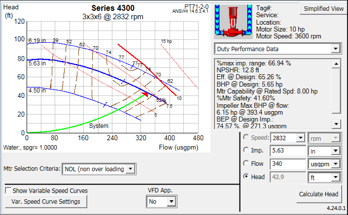
I have a pump that serves a cooling tower. It was designed for 340GPM and 68 feet of head. In the installed condition, it is moving the 335GPM but head pressure is on 43 feet and its VFD is running at 45 HZ (2832RPM, max speed is 3600RPM). At the pump inlet the pressure is barely 1PSI, and the pump has cavitated.

I was not there for the balancing so I am assuming the balancer ran the pump at 60Hz, got too much flow, and they slowed the pump down. Was that the incorrect thing to do? Is the pump size incorrect (68 feet design but only 43 feet drop in the system) How can I keep my flow but get my head pressure up so I don't cavitate?

Here is the design curve, and the operating curve.
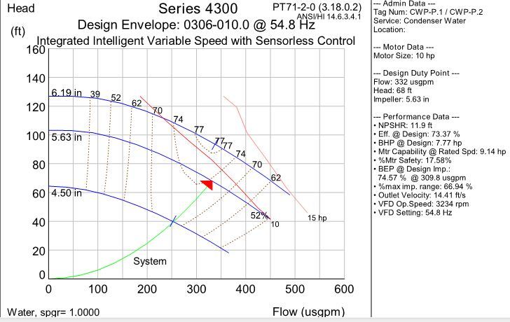
design_dsgzgc.jpg


operating_d4d2ys.png
 
Replies continue below

Recommended for you

From the slightly confused data provided, it seems your pump is indeed slightly oversized for the duty you want ( 340 USGPM). It is far from unknown, especially when the head losses are quite low as in this case, for conservative assumptions to get built into the system curve, which generates a process demand ( 340pgm @ diff head of 68ft), when in reality you only need approx. 43 ft.

Very interesting, but nothing to do with cavitation. Your delivery head pressure has nothing to do with the inlet pressure which is what is causing your cavitation.

The pump is running towards the RHS of the pump curve which can increase NPSHR and also increase the cavitation curve quite a lot more than NPSHR. Its also running at a flow> the BEP which is not a great idea.

You don't say what the temperature of the incoming fluid is, but with a hot water system it's not hard to run into cavitation issues, which, as said are NOT the same as NPSH.

~Ask the vendor for a cavitation curve for your pump. You might be quite surprised.


Remember - More details = better answers
Also: If you get a response it's polite to respond to it.
 
Takket3, Littleinch is right. It is unlikely to be a cavitation issue and there is no point increasing your discharge head losses for nothing. You will only add to the power cost.
Remember that NPSHR is based on ABSOLUTE pressures, not gauge pressure. So you have an additional 30 feet up your sleeve that you probably didn´t realise. Take away the losses, temperature effects, altitude of the installation, etc., and you should still be OK.
I think I know why you presented TWO DIFFERENT pump curves. The first you mentioned is the design. The second is the actual selection which is a different curve. Not sure what happened to the original series 0306-010.0 design model but that would have been much better suited to the 340 gpm. Now you are stuck with a pump that will always be operating to the right of BEP.

Aside from changing the pump to a model that is better suited to pump 340 gpm, I think the best option you have is to lower the design flow rate to about 280 gpm IF the cooling tower circuit is OK with that. Just drop the rpm further or trim the impeller. Don´t do any more than these options. I am assuming of course that cavitation is occurring.

 
What's the water temperature?

Remember - More details = better answers
Also: If you get a response it's polite to respond to it.
 
How did you establish it is cavitation?
Have you investigated imposing some additional head on the system by throttling a discharge valve?

It is a capital mistake to theorise before one has data. Insensibly one begins to twist facts to suit theories, instead of theories to suit facts. (Sherlock Holmes - A Scandal in Bohemia.)
 
Although it won't help you system too much, you really need to look at raising the inlet head if indeed the pump is cavitating.

You might only need an extra 2-3m head on the inlet.

Many questions - no answers yet.

Remember - More details = better answers
Also: If you get a response it's polite to respond to it.
 
As usual insufficient data and nothing coming back, so we are spinning wheels over nothing.

It is a capital mistake to theorise before one has data. Insensibly one begins to twist facts to suit theories, instead of theories to suit facts. (Sherlock Holmes - A Scandal in Bohemia.)
 
So... update to this............... Despite the design head the actual resistance the pump sees is only the 45 ft. So the balancer slowed down the VFC because the flow was too high.

I don't think the cavitating has anything to do with the pump discharge. There is a 3-way bypass valve from the return back to the supply. It is more or less about 10 feet above the pump. The cooling tower basin is more or less 10 feet above the bypass valve. I read a few places (tower manufacturer install guides) that if the bypass doesn't empty into the tower sump, that it can actually go into negative pressure and draw air into the system, and this air gets into the pump.

See page 9:
So we are going to experiment with modulating the bypass from 0% to 100% and see if that effects the inlet pressure at the pump.
 
We know discharge won't make any difference. Air in the inlet usually helps cavitation, but might make some similar noises. Opening the bypass may well make a considerable difference, its just wasting energy so just crack it a little bit at a time to get the lowest flow you can which makes a difference.

Remember - More details = better answers
Also: If you get a response it's polite to respond to it.
 
If you want meaningful advice, you will need to supply a drawing of your layout, water levels of the inlet and discharge side relative to the pump centreline, and an NPSHr curve for the pump and your calculated NPSHa data.
Without it, it is just running in circles and applying a shotgun approach to the problem / cure.
Your call,there are a lot of members with pump trouble shooting experience in E-T but little experience in fortune telling.

It is a capital mistake to theorise before one has data. Insensibly one begins to twist facts to suit theories, instead of theories to suit facts. (Sherlock Holmes - A Scandal in Bohemia.)
 
Artisi calls it right as .

See my strap line, but I really like the fortune telling bit....

Remember - More details = better answers
Also: If you get a response it's polite to respond to it.
 
You are ok. The 1 psig at pump inlet is equal to 2.3 ft water head + 33.9 ft water head from athmospheric pressure = 36.3 ft vs the 12.8 ft NPSH required.

The design flow is met & the VFD is properly set so pump is not wasting energy. Lower head at start is to be expected because the new pipe & chiller tubes are not yet fouled. Open water piping system will corrode more than closed system so de sign allows for more pressure drop.

Make sure air has been bleed from the piping system. The bypass valve is normally open with chiller off. Set controls to gradually close valve when pump start & when condenser water supply temperature is above 60 F. Valve should not be controlled to modulate because during winter lowering the flow to the cooling tower will promote ice built up in the cooling tower fill.
 
Lilliput1. You neglect the vapour pressure of the fluid. This is,I assume, Hot water. How hot the OP hadn't told us, but if close to boiling point, vapour pressure can be significant.

Hence your opening statement is without basis.

Also NPSH is not the same as cavitation. Cavitation often/usually happens at a higher head than NPSH, sometime by several feet.

Remember - More details = better answers
Also: If you get a response it's polite to respond to it.
 
Sorry I thought the pressure gauge at pump suction with pump operating will incorporate the vapor pressure of the fluid. From Cameron Hydraulic Data: "on an existing installation the NPSH available would be the reading of a gage at the suction flange converted to feet of liquid absolute and corrected to the pump centerline elevation less the vapor pressure of the liquid in feet absolute plus the velocity head in feet of liquid at point of gage attachment."

Gage reading in ft of water absolute = 1/.433 + 33.96 = 36.27

Correction for gage to pump centerline elevation = say + 4/12 = 0.33 ft

Deduct absolute vapor pressure of condenser water at 85 degrees = - (1.213 in Hg absolute x 1.13406 ft H2O/in Hg) = - 1.376 ft of water absolute

Add velocity head in ft of water = .00259 x (GPM)^2 / (inch dia)^4 = .00259 x 340 ^2 / 3.068^2 = 3.38 ft

NPSH = 36.27 + 0.33 - 1.376 + 3.38 = 38.60 ft vs 12.8 NPSH required so pump should not cavitate.

You should not hear gurgling sound at pump.
 
It's all well and good carrying on the discussion, but where is the OP - Takket3, hasn't been sighted now for many days, has he solved the problem - who knows, but thanks anyway we are enjoying ourselves.

It is a capital mistake to theorise before one has data. Insensibly one begins to twist facts to suit theories, instead of theories to suit facts. (Sherlock Holmes - A Scandal in Bohemia.)
 
If it's 85F then ok, but if it's 85C then it's a different story....

Remember - More details = better answers
Also: If you get a response it's polite to respond to it.
 
Status
Not open for further replies.

Part and Inventory Search

Sponsor