Eng-Tips is the largest engineering community on the Internet

Intelligent Work Forums for Engineering Professionals

  • Congratulations waross on being selected by the Tek-Tips community for having the most helpful posts in the forums last week. Way to Go!

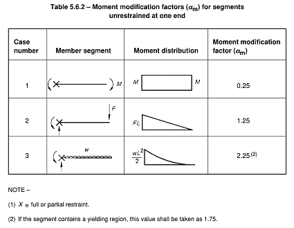
Cb and Lb for cantilever column.

Status
Not open for further replies.

Jandra11

Structural
Jun 18, 2017
109
0
0
PH
Hello, guys, I'm a bit confuse of what parameters should I consider in a cantilever column that is not braced at the free end. This structure has a concentrated load at the free end. Do I need to check the column for lateral torsional buckling, or this checking is only applicable for beams? Any suggestion and comments are welcome. Thank you in advance
 
Replies continue below

Recommended for you

Does the concentrated load put the column into bending or axial compression?

If the former, it's a beam-column, so LTB applies. Cb = 1.0 (or maybe less!) and Lb at least as long as the physically unbraced length.

But if the latter -- LTB doesn't apply. Your will need to consider global buckling, local buckling, maybe torsional buckling, and second order effects ... but not LTB.

----
The name is a long story -- just call me Lo.
 
Thank you LO, the force causes the column to bend. CB can be less than 1? I thought to assume Cb as 1 is already a conservative approach. Btw i found this trendLink They said that Lb should be multiplied by 2?
 
Theoretically I'd say the unbraced length depends on where the load is applied in relation to the member shear center. If its a destabilising load (applied above the shear center) then Lb factor would be 2, if its a stabilising load (applied below the shear center) then the Lb factor would be 1.

Cb can be less than one. For a cantilever with just a moment at the free end it's less than 1 I believe. It's over 1 for your case with a point load at the unrestrained free end, so taking 1 is conservative.
 
What shape is the member cross-section and is the concentrated load causing bending about the strong-axis? Lateral-torsional buckling is not a concern for round HSS and likely not a concern for rectangular HSS bent about the strong-axis. It also would not be a concern for members bent about their weak-axis. What is the governing building code? If IBC, then AISC 360-10 would have you use Cb = 1.0 for a cantilever where the free end is unbraced. I am unaware of a condition where Cb would take on a value less than 1.0. A uniform (constant) moment diagram is equivalent to Cb = 1.0 and that is the most severe moment diagram. Other loading conditions would result in a Cb value greater than or equal to 1.0.
 
If theres any moment you should check it for LTB as well as axial compression. If its a hollow section its very unlikely to be critical as Hokie mentioned (unless the aspect ratio is ridiculous).

From UK perspective, this is a great program to calculate Mcr, I'm not sure how you american/canadian folk generally calculate it though.
For speed I like just using the blue book to get MbRd and be a bit conservative Strictly you should calculate Lcr properly for a cantilever but in a pinch I would just use 2L. BS5400 has the relevant tables for various load conditions, which you can then use to calculate Lamda_LT and thus your buckling reduction factor.
 
A uniform (constant) moment diagram is equivalent to Cb = 1.0 and that is the most severe moment diagram

This is only true for a segment with restraint at both ends, for a cantilever it's also the worst case as I posted earlier, but Cb is less than 1.0 for a cantilever case with no restraint at the ends. Will prove later with mastan2 and post back, my code says to take this case as Cb=0.25 for information.
 
As far as I understand, for a beam element restrained against twist (particularly the tension flange) at the fixed end, Lb = L and Cb = 1.0 is appropriate. As far as I understand, it's beneficial to restrain the section against twist at the free end (especially for large tip loads or moments), but not necessarily required.

The odd cases come up when the restraint at the support is less than idealized, and/or when load is applied other than at the shear center. See the thread Jandra11 linked above (and/or the SSRC -- in the 6th ed, 5.2.4 and 5.2.9) for some discussion of that.

(Different authors and codes adjust for these factor using Cb, effective length factors K*Lb, or just computing a critical moment Mcr directly -- everyone is doing the same thing, in different ways).


----
The name is a long story -- just call me Lo.
 
As promised see the attached output from Mastan2. Comparing a constant moment gradient for a cantilever case and the standard Cb = 1.0 constant moment gradient case.

As noted previously this proves Cb can in fact be less than 1.0 under certain conditions. Obviously a pure moment applied to the end of a cantilever is not too common in practical structures!

The calculated Cb = 0.68 is still miles better than the value my local code (NZS3404) requires you to take for this configuration.

FYI, if it helps for the case of a point load applied to an unrestrained cantilever, my local code takes the equivalent of Cb factor to be 1.25. Alternatively undertake a buckling analysis under your given load pattern and work out the Cb from first principles.

Capture_p0je2t.png


Status
Not open for further replies.
Back
Top