Continue to Site

Eng-Tips is the largest engineering community on the Internet

Intelligent Work Forums for Engineering Professionals

  • Congratulations IDS on being selected by the Eng-Tips community for having the most helpful posts in the forums last week. Way to Go!

CBD Tank - tangential nozzle velocity

Status
Not open for further replies.

crazyjpeters

Mechanical
Dec 7, 2009
15
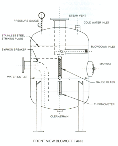
I'm evaluating one of our flash tanks which has experienced concentrated erosion directly downstream of the tangential inlet nozzle.

I've seen this posting regarding a similar topic:

The tank I'm evaluating has a blowdown throttling valve discharging into the tank. Rather a small nozzle length, and does not increase in size. For numbers, this is a 2600psi to 100 psi tank letdown. 60,000 lb/hr water/steam going into a 1.1" ID nozzle. This to me seems extremely small. Judging by that other thread, and most other literature I can find on flash tanks / separator tanks, to keep the velocity down, I'd need something like an 8inch nozzle after my throttling valve.

My question is:
-has anyone run into a similar situation? Perhaps there's a legitimate reason to locate it so close to the tank and have high velocity. Hoping that all the flashing occurs in the tank and no flashing steam rocketing the condensate through the circumferential wear plate?

I'm struggling to find any design guideline that would recommend a nozzle that small, but have a hard time believing that a big-time consulting firm would screw something like this up. 30yrs after commissioning, so hard to really get answers from them.
 
Replies continue below

Recommended for you

elketnioebythunoiwenibironewrn_tr_ennweiroiuerhire_lwjtnjl_jnewrkl_tbj_lewjnh_ltbj_lt_leb_woitiuewoiwtbewntierwitoperwupoe_jvpgpm.gif


Does the tank have an internal, stainless steel "striker plate" ?

The striker plate is meant to be the sacrificial target for the blowdown and usually runs 270 degrees around the inside of the tank. Welded on all four edges .... The plate thickness is typically the same as the tank wall.

This is a very common feature for boiler blowdown/blowoff tanks .... I have specified many tanks with this feature

MJCronin
Sr. Process Engineer
 
And are mandatory in Canada for tangential nozzles, per CSA B51 (7.5.3.6), although it doesn't require stainless.
 
The tank construction is much the same as you assume. 3/8" carbon tank shell, but only a 3/32" 304-SS circumferential liner (360degree in this case). Our problem originally was that we blew right through it in 7 months. My original assumption was that the nozzle velocity was too high. Indeed, the flowmeter data we have indicates that we were blowing down at a rate at least double what the tank was spec'd for. This seems to be due to a change in goals (blowdown tank was originally to lower silica, but the lab blows down more in order to limit conductivity, which appears to be a harder target to meet).

I've run some software models to try and verify what is going on in that nozzle, since conditions would tell me that it flashes to about 50/50 steam/water in the tank, therefore it's basically 2-phase annular mist regime. If it is mostly defined by the steam velocity then, the velocity would be extremely high (2000 m/s?). The model is predicting that flow is choked (which I sort of thought would be the case).

Now what to do about it? What I had originally intended was to increase nozzle size to 8" to drop the velocity way down, but un-choking the pipe may have the opposite effect, flashing more, without choked flow would tend to increase velocities. And literature seems to suggest that the whole design intent is to have it more liquid, with high velocities creating a centrifugal separation around the plate.

One option that seems promising is to introduce a second nozzle at 180deg to handle the additional flow. And possibly increase the thickness of the tank liner. 3/32" seems way too thin. There's tanks I've seen with 1/2" liners.
 
OK .... now we have the rest of the story ...

Suggest that since the tank must be replaced that you explore:

- Larger diameter tank

- Harder material for striker plate (mechanism for degradation is erosion... stainless is fairly soft)

I would contact various vendors of blowdown tanks and ask for their suggestions.

Some years ago, I participated in a replacement of carbon steel piping (A53/A106-B) by low Chrome Moly material (A335-P22) in the extraction steam piping at a nuclear power plant.

Perhaps you could explore a thicker blowdown tank of chrome moly material...

Respect us ...Please keep us in the loop regarding your final fix ...


MJCronin
Sr. Process Engineer
 
The likelihood of us replacing the tank is pretty small. What we’d likely do is redesign the nozzle section, cut it out and weld in the redesigned section.

Do you think the 1.5” nozzle for a 60,000 lb/hr flow is still reasonable? Is doubling the number of inlets something worth pursuing?

I know what you mean with the stainless striker plate. I need to find something with better toughness.
 
Even though SS is relatively soft it is very erosion resistant. Part of this is related to the corrosion resistance and part due to the the very high work hardening rates. If you are looking for better then use a Co alloy, either solid or as weld overlay (in two layers).

= = = = = = = = = = = = = = = = = = = =
P.E. Metallurgy, Plymouth Tube
 
Thanks all for the helpful suggestions.

The path forward for now appears to be that we'll replace the elevation of the tank with a prefabricated nozzle section, consisting of a 6" SCH80 nozzle, a 1/2" wear plate, 3/8" shell and 3/8" reinforcement. This all satisfies section 8 div 1 calculations.

I'm a bit disappointed that I wasn't able to find a decent design resource for these tanks. Most manufacturer technical guides give up at flowrates below what I'm operating at, and none seem to address the tangential nozzle design specifically (though they all claim it allows them to reduce the size of their tanks)

Is there anything beyond the Sauders-Brown equation used for sizing these tanks? I fumbled my way through National Board's NB-27 document, and it seems to me to be more aimed at sizing an intermittent blowdown tank.

Some guidelines I've seen:
-vent velocity should be below 50 ft/s to avoid entrainment of water droplets in exiting steam. Noise is an issue above 60 (our vent currently would be about 60).
-vessel diameter should be sized to keep steam at below 11 ft/s to allow fluid drop out.
-50 to 150 ft/s inlet nozzle velocity (PlantEngineering.com) This sort of lines up with our own internal recommendations for flashing condensate piping to be 4,000 to 20,000 ft/min. There's nothing I can find that makes any kind of recommendation for tangential/swirl/cyclonic inlet nozzles with regards to knocking out steam from flashing condensate. There's a Shell resource, but I'm hesitant to use petrochemical guidelines on this, since I've read some comments from members here stating they design differently for steam blowdown vs chemical seperation.

I've approached Penn to get some advice. He's emailed me, but a bit vague, so I'll wait to see where that goes.
 
Feed nozzle criterion I have is for a vapor dominated flow, so it may be not be applicable to this case where the flash mix is 50:50 vapor:liquid.

For a vapor dominated feed, would suggest using either one of the following, whichever is more constraining:
a)Vapor velocity upper limit 70m/sec (erosion limiting constraint, taking credit for inlet tangential feed separation device)
b) For gas dominated feed, rho - V2 <3750 ( in SI units, rho=kg/m3, v=m/sec)

For 2phase feed, would suggest also using ρmix.V2mix<8000, and use the largest dia for all 3 criteria.

At these high velocities, you would obviously need to select some erosion / corrosion resistant materials to get some decent life; lean duplex SS at the least I would imagine for the flash feed nozzle and some portions of the vessel in the direct path of this high velocity stream.

 
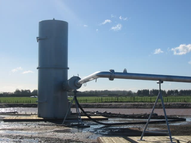
In our applications (much larger flow) we limit the steam phase velocity to around 100m/s in the pipe between the valve and tank. The pipe is also quite long, 12 diameters or more. We still get some wear at the tank inlet and make this section thicker.

Picture_004_Small_y0tk9o.jpg
 
So georgeverghese you've got some guidelines there that are somewhat momentum based. I would think that's what I need to find to really put my mind at ease.

KevinNZ, do you happen to know what steam quality you flash to in the vessel? That might give me some idea.
 
Hi Carzypeters

The setup in the photo is used for steam mass fractions from 15 to 50%.

 
Status
Not open for further replies.

Part and Inventory Search

Sponsor