Continue to Site

Eng-Tips is the largest engineering community on the Internet

Intelligent Work Forums for Engineering Professionals

  • Congratulations waross on being selected by the Eng-Tips community for having the most helpful posts in the forums last week. Way to Go!

CC and CV leds are both lit at same time 1

Status
Not open for further replies.

pmars

Electrical
Jan 30, 2017
10
Does anyone know why both CV and CC LED's are sometimes lit when using my power supply? Scope shows odd waveform whenever this happens. Otherwise, flat line DC, no waveform, everything fine. It usually happens when current limiting knob is just starting to have an effect. Seems like the transition from CV mode to CC mode overlaps and causes a freak out. I can make it go away by over-turning the setting, and then dialing back down. I'm keeping the supply, so looking for a fix... adding a diode or resistor or a left-handed capacitor or some such ;)
(I'm new here, not sure about including photos but giving it a try)
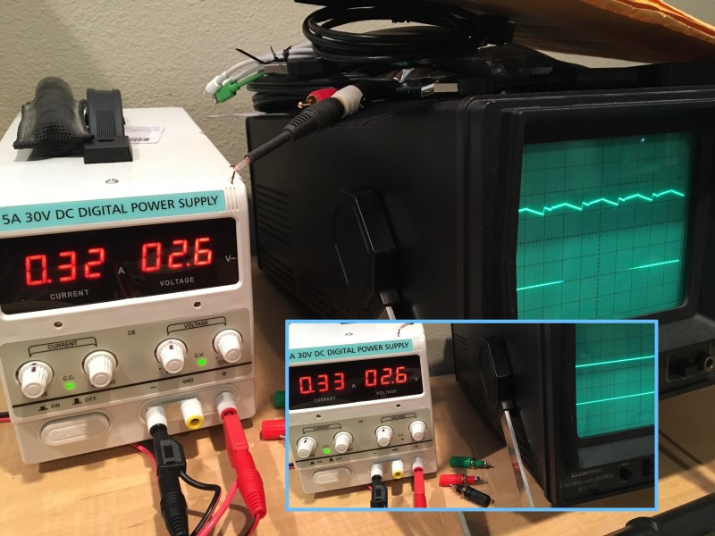
scope-supply_otl3ty.jpg
 
Replies continue below

Recommended for you

That is pretty normal with these low cost supplies. That supply likely has a large capacitor on the output to stabilize voltage during current transitions so it oscillates. That is the reason good supplies cost five times more. Just keep the two limits separated.
 
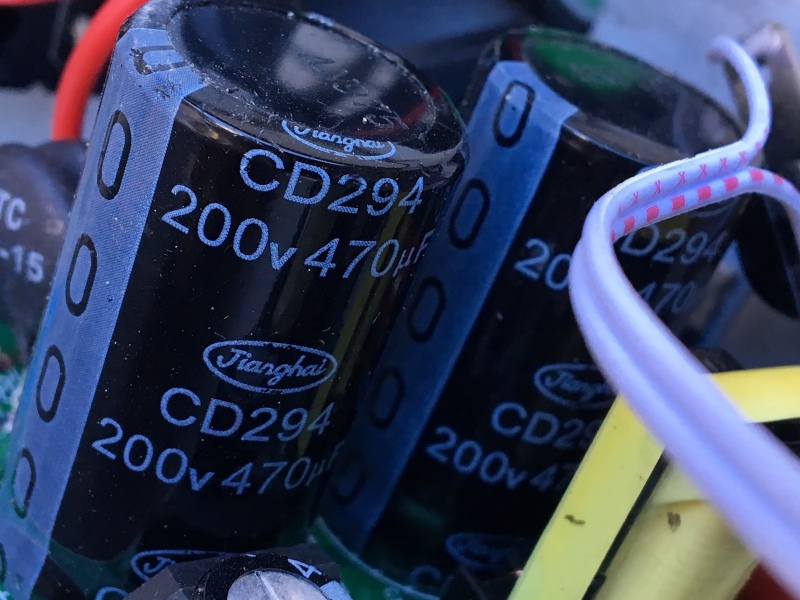
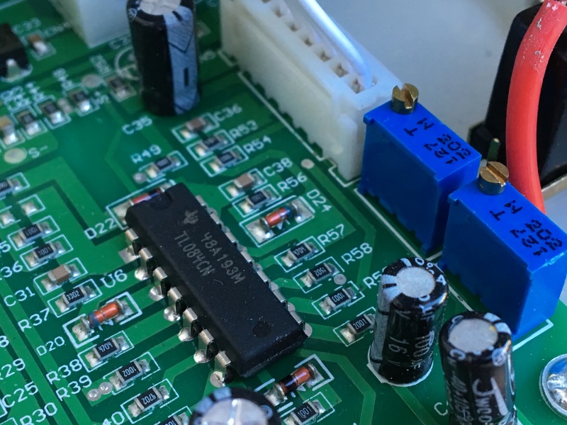
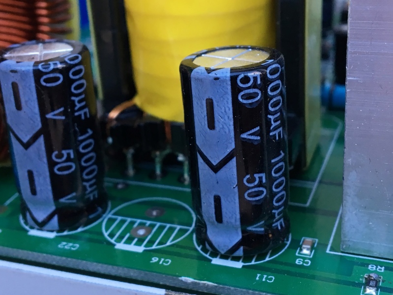
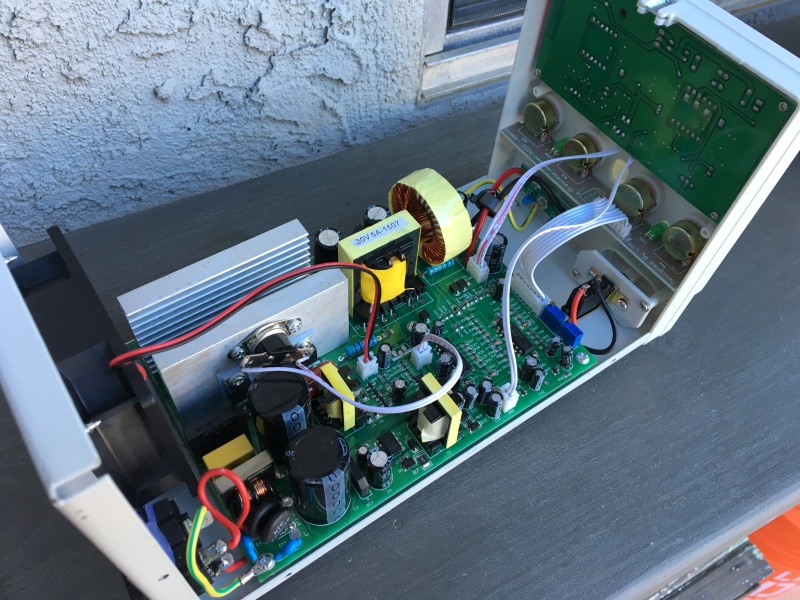
Thanks for your response. Yes it does have some good sized caps, couple of 1000uF and a couple 470uF. Actually there's an open spot on PCB to add a third 1000uF. I was thinking this might be a good idea, but after reading your reply maybe not. What about isolating, or separating the sensing circuit from the supply a bit, so it might not be so sensitive? Looks like the pertinent chip is a TL084CN Vcc'd at 24V. I'm currently attempting to reverse engineer the circuit and determine if anything deviates from TI recommendations. I don't know, seems like this op-amp is having trouble with a signal that's not real clean to begin with. Maybe a small cap added somewhere or a missing cap. Wish I was better at this. Thanks for your input, if all else fails, I'll just respect it's limitations and try another slightly more expensive PS. I do like that this one is a switching PS and has no huge transformer.

IMG_3515_k7ag7u.jpg


IMG_3516_wm2gww.jpg


IMG_3517_vm2qrc.jpg


IMG_3520_cgeun3.jpg
 
"You should not run power supplies at both CC and CV limits."

That's my point exactly. But in dialing things in, invetiably I run into the point where the 2 controls overlap and the PS output freaks out, causing a potential disaster for delicate circuits. I'm determined to find a cure. It should be impossible for both LEDs to be lit at same time. The transition is flawed somehow.
 
Is it possible that the PSU is bouncing between the two modes at a frequency faster than your eye can resolve? The LEDs may not be on simultaneously but will appear to be if they are alternating faster than a few Hz.
 
I suppose it's possible for the LEDs to be flickering back and forth, but if they are, it's still an indication that the CC or CV circuit is doing the same thing. The CC limiting is not doing it's job while this is happening. Raising the voltage dial allows the voltage and current to rise until the CV led goes out and the CC led is on full... then the current reading comes down and the Current dial is back in control. That transition range is not safe because the voltage can go from 7 to 10 before it settles down and current can increase by 50% during that same transition. Leaving the PS in this weird transition state causes the crazy waveform which can't be good!

It could be like a vibration, not locking in on one or the other state. Like an out of balance car tire vibrates at a specific RPM but is OK before and after. There is a simple solution to this... I just have to find it.
 
Can anyone recommend a direct replacement for the TL084... a newer/better quality op-amp might help.
 
"invetiably [sic] I run into the point where the 2 controls overlap and the PS output freaks out"
As the doctor said as I complained about the pain that occurred when I moved my arm thusly, "well, then don't move your arm thusly."

Perhaps you should explain WHY you need to do both and what the application is. Almost all circuits have variances in operating conditions, depending on modes and functions being exercised, so constraining both voltage and current is typically an unwise thing to do.

TTFN (ta ta for now)
I can do absolutely anything. I'm an expert! faq731-376 forum1529 Entire Forum list
 
I'm not intending to run this in both modes simultaneously, the power supply has a problem with the automatic CC & CV circuit. In normal operation, the Op-Amp somehow switches between the 2 when a limit is encountered. In general use, Voltage is Controlled so the CV LED is lit most of the time to indicate that you are setting the voltage. However, as a safety feature, you can also set the max. allowable Current so if a circuit or device begins to draw more current than what you have set, the "Constant Current"(CC) circuit kicks in and limits the current by reducing the voltage as a function of ohms law. So if you had PS voltage set to 12V and current limit set at 1A, everything would be good as long as your load remained at 12 Ohms or higher, but if your load developed a problem and dropped to 6 Ohms (which would draw 2A at 12V), the Power Supply CC setting would not allow this and due to its' current limiting feature, the output voltage would automatically drop to 6V in order to maintain the 1A CC limit that was set. Limiting is supposed to be indicated by an instant change from CV to CC mode. However this particular supply is getting caught in limbo between current limiting and no current limiting and the result is a weird output wave form. The only way to make it stop is to turn up one of the dials and then back it down to proper voltage or current setting... thus destroying your delicate circuit project! Hope this clarifies the situation.
 
When both LEDs are lit at the same time, it indicates a huge problem since the op-amp is not supposed to be able to be in both states at the same time. So I am assuming, as was suggested by ScottyUK, that the Op-Amp control circuit is probably bouncing or oscillating between on/off or +/- or whatever. I am attempting to trace a few of the components in hopes of identifying some anomaly b y comparing to known op-amp data sheet schematics. At the moment I'm questioning the need for a 100uF cap in series with a 15K resistor between pins 10 & 11. And what role the 2 multi-turn pots play...perhaps a reference voltage needs adjusting. My goal is non-destructive experimentation and observation. Thinking about replacing the TL084 with an LT1359. :)
 
The only reason it's bouncing is because the two limits are interacting, which means that you are setting one of them too tight. Typically, for most electronic circuits, you set the voltage and the current limit acts like a fuse, which means it's only there to prevent catastrophic failure, which means that the current limit is easily a factor of 2x or 5x the operating current, which means that there should NEVER be a CC condition unless the circuit or the PS has failed.

TTFN (ta ta for now)
I can do absolutely anything. I'm an expert! faq731-376 forum1529 Entire Forum list
 
The operation of the LED and the mode of operation are not in directly connected to the operation of the power supply, close but not directly. Changing the op amp will make no difference. Given that it has an op amp, the voltage error and current are combined together using two diodes. When they get close, they interact. Before you get too bent out of shape over this issue, I suggest you hook up a FET or relay to a load resistor of an amp or more and switch the load on and off 50% duty cycle and see how that looks on your scope. Look at undershoot and overshoot on transitions. That is what I would be concerned about.
 
"....should NEVER be a CC condition unless the circuit or the PS has failed." I agree, it's just that adjusting the Current Dial down to get an idea of where the limit is set, throws the PS into this weird state. It's not proper behavior and causes dangerous output in my opinion. I can certainly work around it but I'd prefer to find the cause and hopefully fix it.

"Look at undershoot and overshoot on transitions. That is what I would be concerned about." Good point, the PS may be so crappy in the first place that I'd be better off using it for parts or to run christmas lights or something :)

Thanks for your input, I'm gonna check a few caps today to verify no obvious bad ones, and if time permits, maybe give those 2 multi-turn pots next to the Op-Amp a couple spins in both directions and see what happens. (I'll note the resistance settings before hand of course) Will update with anything new.
 
" it's just that adjusting the Current Dial down to get an idea of where the limit is set"

This does not compute; the Current Dial IS the current limit, so when you hit that point, you're telling the power supply that it's not allowed to increase the voltage to supply the power demand, and it's not allowed to increase the current either. That's a nonsense operating condition.

TTFN (ta ta for now)
I can do absolutely anything. I'm an expert! faq731-376 forum1529 Entire Forum list
 
Ok I'm done for now... I've tried to explain this in common sense terms several times but you are not understanding the operation of the power supply for some reason. Nearly all power supplies have this exact same feature (CC & CV) limiting. A very useful feature, however mine doesn't work properly. Have a nice day :)
 
A more expensive supply would have 'foldback current limiting', where, when the current exceeds the set threshold, the supply reduces the output to a level that probably won't forward bias a silicon diode, thereby protecting sensitive circuits.

You would typically set the foldback, against a resistor load, to occur at a current somewhat higher than the worst-case current you expect to see in the circuit under development, then leave the current setting alone, until you wish to power a different circuit.

Your supply is clearly trying, to the best of its ability, to honor both of your requests for a particular voltage limit and a particular current limit, but you are confusing it by twiddling the knobs until it gets into a condition where both limits are starting to kick in, and it's oscillating between the two, undecided, or maybe vacillating would be a better word.

There is nothing 'wrong' or 'broken' with your supply; you are just confusing it.


Mike Halloran
Pembroke Pines, FL, USA
 
Yea, I think I'm just gonna have to live with it until I can find a deal on a better PS. I have watched several YouTube demos on similar supplies and what I've noticed is that the CC and CV LEDs seem to lock in very quickly with virtually no overlap. Like a SPDT switch. You can have either A or B, but not Both. Anyway, at this point I'm not going to spend more time on it. I've tested nearly a dozen Caps and reflowed a few suspicious looking solder joints and no change so I'm putting it back together. I'll be careful not to let those limits overlap. Thanks to everyone that commented and offered suggestions, I appreciate your time! - Peace
 
Status
Not open for further replies.

Part and Inventory Search

Sponsor