Continue to Site

Eng-Tips is the largest engineering community on the Internet

Intelligent Work Forums for Engineering Professionals

  • Congratulations SDETERS on being selected by the Eng-Tips community for having the most helpful posts in the forums last week. Way to Go!

Center Constraint

Status
Not open for further replies.

Nahid Mubin

Mechanical
Mar 24, 2023
15
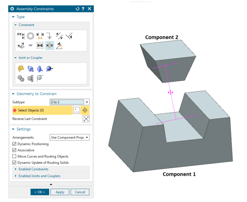
I want to make a component to be in the center of another component. But the center constraint doesn't work. The constraint become pink in color and shows error. I have used 2 to 2 center constraint where I selected 2 faces from component1 and another 2 faces from component2. Note that the component1's faces aren't parallel with the faces of component 2. Is it the reason behind the error? If so then how can I put the component1 in center of component2. Check the following picture-


Screenshot_2023-10-21_141937_zwkqov.png
 
Replies continue below

Recommended for you

Yes, I suspect that it has to do with the non-parallel nature of the faces.

John R. Baker, P.E. (ret)
Irvine, CA
Siemens PLM:

The secret of life is not finding someone to live with
It's finding someone you can't live without
 
Use the mating edges.

First pair from the inserted part leading face, second pair from the receiving part mating face.
 
Using the edges in this case is a good suggestion.

Also note that you can add geometry specifically for constraints in your part file. For example, when working with a compression spring, there isn't much in the model that is useful for assembly constraints. In this case, I'll add a cylinder to the part around the spring geometry for reference; I'll add it to a new ref set called "constraint geometry" and remove it from the model ref set. When positioning the spring in the assembly, I change to the constraint ref set, add the desired constraints and then change back to the model ref set.

www.nxjournaling.com
 
If the faces are parallel AZPete's method will work unless you need space between the components. If you need space or the faces are not parallel, I would add a bisector datum plane to each component, then align or mate the datum planes in the assembly.
 
Status
Not open for further replies.

Part and Inventory Search

Sponsor