Continue to Site

Eng-Tips is the largest engineering community on the Internet

Intelligent Work Forums for Engineering Professionals

  • Congratulations KootK on being selected by the Eng-Tips community for having the most helpful posts in the forums last week. Way to Go!

Center wire for EMC common mode return path 3

Status
Not open for further replies.

Jensdsds

Electrical
Jun 9, 2021
33
Hello,

I am looking for advice/knowledge on EMC common mode reduction in a VFD motor setup.
The power cables are in the 300mm^2 sizing.

My question is:
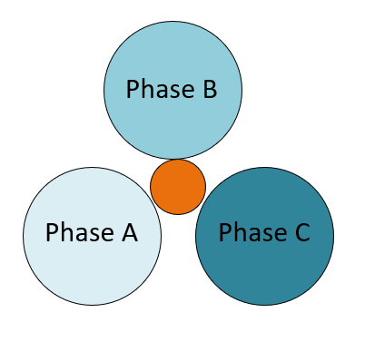
Is a combination of a center wire inside a trefoil consisting of 3 single core cables phase ABC, and a well connected cable ladder forming a PEC(parallel earth conductor) a better solution for common mode return path, compared to shielded cables.

I know both cable solutions have various negatives/positives, so i am mainly looking for some experience with a center wire solution.

Thanks in advance.
 
Replies continue below

Recommended for you

Hello Jensdsds

The common mode output current from a VFD, is due to capacitively coupled current impulses from the individual voltages steps on the motor windings to the motor frame.
These impulses amount to quite high amplitude, very short impulses (due to the rate of change of the voltage waveform) at the switching frequency of all three phases.
Typically, a frequency plot of these currents yields that the noise power is centered around the 100KHz area and covers a broad frequency range.
A very effective means of mitigation, is to ensure that there is a very low impedance (at say 100KHz) between the motor frame and the VFD frame. This assumes that the VFD has either a good capacitive path between the frame and the DC Bus, and/or the frame and the three phase input.
To ensure a low, high frequency impedance between the VFD frame and the motor frame, we use the skin affect of the conductors and provide a very large surface area return path over the complete return path.
The use of a correctly terminated screen around the conductors, or a metal conduit, is an economic and easy way to ensure the return path has a low impedance at high frequencies.
It is important that the screen is continuous and that it is terminated by clamp connection (360 degree termination) and that pigtail terminations do not occur anywhere in that path.
A similar surface area following a different path can also work well. Other metal surfaces such as metal pipes, metal ladder rack, braid or bar can work provided that he surface area is as large as the screen opened out over the full return path.
It is not a case of using the screen to prevent radiation, it is to provide a low impedance path at 100KHz and above.
Foil screens are not an effective return path because the foil is too thin, so braid or braid plus foil. The center conductor is primarily for Protective Earth only.
Further improvements will be made by adding common mode ring filters around the three output phases (but not earth) where all three conductors pass through the ring(s) together.
NB : Get the earth return path right before adding the common mode rings for best results.

Best regards,

Mark Empson
Advanced Motor Control Ltd
 
Hello Marke
Thank you very much, for a well explained and detailed answer!

It was very useful, i do have some follow up question:

[ol 1]
[li]I know a project where an engineer installed a center wire in the middle of a single core trefoil setup.(Along with a correctly terminated cable tray) 300mm^2 phase, 16mm^2 center wire. He claimed that the wire was purely for common mode return, and the system had installed PE wires inside the same cable tray.(see picture below)[/li]
Sk%C3%A6rmbillede_2021-06-23_082339_rmgc2r.png


[li]After creating the best return path possible, how does one in practice figure out if you are in the need of a common mode ring filter? Can you do a short test run to measure the current+noise? Or is that too risky, not knowing the level of common mode noise in the system.[/li]
[li]Why are shielded cables not used for large vfd motor drives. (300mm^2 sizes) Is it mainly due to the high current levels inducing losses in the shielding, or is it the higher capacitance creating higher dV/dT levels? [/li]
[/ol]
 
I would say that the center wire and the geometry is an attempt to keep the capacitive impedance to earth balanced for each phase in much the same manner that an EMC cable has three earths evenly distributed rather than a single earth wire and uneven capacitance.

Mark Empson
Advanced Motor Control Ltd
 
OOPs. pressed submit too soon. Thats what happens when you are trying to get an answer out between phone calls.

2. If there is no interference present, then no rings are required. If there are issues, then try the rings.
My measuring device that I use in the field, is a portable battery operated AM radio. Tune onto a weak station and compare the level of interference with and without the rings,

3. Shielded cables are used for larger drives, it just depends on the installer, and the materials available.

Best regards,

Mark Empson
Advanced Motor Control Ltd
 
Status
Not open for further replies.

Part and Inventory Search

Sponsor