Continue to Site

Eng-Tips is the largest engineering community on the Internet

Intelligent Work Forums for Engineering Professionals

  • Congratulations IDS on being selected by the Eng-Tips community for having the most helpful posts in the forums last week. Way to Go!

Centerline misalignment shell/head Fig UW.13.1

Status
Not open for further replies.

ElCidCampeador

Mechanical
May 14, 2015
269
Hi,

Pressure vessel designed acc. to ASME VIII Div.1, material SA 516 Gr.60.
This vessel has a shell and an ellipsoidal head 2:1 that have to be welded with a butt weld according to fig. UW 13.1
In particular:
+Shell: I.D. 1220mm
O.D. 1390mm
Thk. 85mm
+Head: I.D. 1200mm
O.D. 1380mm
Starting thk.90mm
M.A.F. thk: 80mm
I'm verifying if condition of figure UW-13.1 is ok:

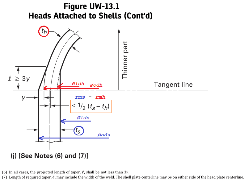
(difference between shell/head centerline)<=1/2(th-ts)
In this case: 7,5<=0,5*(90-85) -> 7,5<=2,5 FALSE

Now I have to weld shell with head, what should I have to do to make it acc. to code? Is necessary an internal/external transition?

Thank you
 
Replies continue below

Recommended for you

Because you have a 5mm offset you do need a 3:1 taper between head and shell. If your weld bead is 15mm wide this 3:1 transition can be accommodated completely within the weld.
 
Don56 said:
Because you have a 5mm offset you do need a 3:1 taper between head and shell. If your weld bead is 15mm wide this 3:1 transition can be accommodated completely within the weld.

ok, for me tapering is not a problem.
What I say is that the centerlines of the head and the shell, acc. to UW-13.1, seem to be indipendent from the weld bead/tapering and depend only on the original centerlines of head and shell (th and ts are intended as "nominal thicknesses" as I understand). This means that the value of 7,5mm is fixed by the real dimensions of components and it can't be changed. Is it a correct interpretation? How can I change the relative position of the centerlines so that the difference could be less?
 
ElCidCampeador, I am taking your head skirt thickness as 90, per OD and ID given.

I agree your centerline mismatch does not meet UW-13 limit, 2 1/2 mm.

It looks to me like you are going to have to match OD's or ID's, either one.

Regards,

Mike

The problem with sloppy work is that the supply FAR EXCEEDS the demand
 
The centerline misalignement according UW-13(b)(3) and fig UW-13.1, to me seems the difference in the mean radius of shell and head, which would be different from what you said (I mena it is not 7.5mm).

ts = 85
ods = 1390
ids = ods - ts*2 = 1220
rms = (ods+ids)/2/2 = 652.50

th = 80
odh = 1380
idh = odh - th*2 = 1220
rmh = (odh+idh)/2/2 = 650

requirement:
rms - rmh = 2.5 <= 1/2*(ts-th) = 2.5
Verified
 
SnTMan said:
It looks to me like you are going to have to match OD's or ID's, either one.

That's the problem: how?

Turning internally the entire head up to I.D. 1220mm?

Or is it enough adding weld metal to the outside skirt head diameter up to O.D. 1390mm? But in this last case the centerline is still the starting one because only skirt head thickness is increased
 
Vikko said:
th = 80
odh = 1380
idh = odh - th*2 = 1220
rmh = (odh+idh)/2/2 = 650

requirement:
rms - rmh = 2.5 <= 1/2*(ts-th) = 2.5
Verified

mmm I don't know if it's correct, because ASME talks about "nominal thickness" not minimum. Moreover, skirt head is usually more thickened than the rest of the head so that it could be approximated with the starting thickness, in my opinion. So idh=1200, rmh=645, then rms - rmh =652,5-645=7,5mm. What do you think?
 
ElCidCampeador, I'm not certain either option meets the letter of the Code.

The head is nominally the thicker part, but... Shell cylinder is larger OD. You'd need to taper it 30mm length. Head is smaller ID, you'd need to taper 20 60 mm length. At this, you'd still have the 7 1/2 mm mismatch at CL.

Perhaps turning the head ID for the full skirt length, and then 1:3 taper into the tangent (if needed) is the most practical fix, but better check required thickness. Better get your AI to bless it before proceeding.

Good luck.

Mike

The problem with sloppy work is that the supply FAR EXCEEDS the demand
 
All dimensions shall be after forming the head.

Regards
r6155
 
I suspect that's what we've got now. Why would you order out such dimensions?

The problem with sloppy work is that the supply FAR EXCEEDS the demand
 
SnTMan said:
I suspect that's what we've got now. Why would you order out such dimensions?

Because supplier of head hot formed it using a hot forming press which can make heads only in a specific range of dimensions. The solution I choose was the closest to dimensions required in the drawing and with the best fit to shell. Unfortunately I noticed the problem with Fig UW.13.1 only later.
 
This is UW-13.1(j) which I think is the closest to the dimensional problem you got. I think it is as I said.
Fig_UW-13.1_j_xiiebt.png


Also the definition is UW-13(a) are the following:
- th = nominal thickness of head
- ts = nominal thickness of shell
 
Vikko said:
Also the definition is UW-13(a) are the following:
- th = nominal thickness of head
- ts = nominal thickness of shell

yes nominal thk, not M.A.F. (see definition in mandatory appendix 3)
Moreover figure j is not applicable, because in my case th=90 and ts=85 (figure m is more appropriate I suppose)
However, I don't think it's very clear how to determine odh and idh, because the only dimensions I have are the REAL dimensions of the head after forming
 
M.A.F. is the thickness after forming or the nominal thickness ? In any case, you should use the nominal thickness. And according to fig. UW-13.1, the centerline, is the projection according to this nominal thickness (th).

According to Appendix 3 / thickness of vessel wall: (c) the nominal thickness is the thickness ... either the thickness shown on the Material Test Report {or material Certificate of Compliance [UG-93(a)(1)]} before forming, or the measured thickness of the plate at the joint or location under consideration.


Vikko said:
M.A.F. is the thickness after forming or the nominal thickness ? In any case, you should use the nominal thickness. And according to fig. UW-13.1, the centerline, is the projection according to this nominal thickness (th).

According to Appendix 3 / thickness of vessel wall: (c) the nominal thickness is the thickness ... either the thickness shown on the Material Test Report {or material Certificate of Compliance [UG-93(a)(1)]} before forming, or the measured thickness of the plate at the joint or location under consideration.

M.A.F. is the minimum thickness after forming (which is a result from calculation), NOT the nominal thickness of the plate.

All references in UW-13.1 are to NOMINAL THICKNESS, so I think that what you're saying is not applicable
 
Ok, so I do not think you can mount these 2 parts together according to the code, as they are now, because of this shape and dimensional requirement. Change the nominal thickness of the head by cutting and grinding on the internal diameter of the head, so to bring the centerline more aligned to that of the shell.
 
If you forming the cylindrical shell before forming the head you are working wrong.

Regards
r6155
 
r6155 said:
If you forming the cylindrical shell before forming the head you are working wrong.

I haven't formed shell yet, but I have to respect I.D. of shell because of internal cartridge dimensions (fixed by client)
 
In the future I suggest you cold form the heads to the correct dimensions then Post Form Heat Treat if required.
 
david339933 said:
In the future I suggest you cold form the heads to the correct dimensions then Post Form Heat Treat if required.

Supplier told us that the only way to realize this kind of head with these thk and diameter is with hot forming: it's impossibile to form it without heating it
 
Status
Not open for further replies.

Part and Inventory Search

Sponsor