Continue to Site

Eng-Tips is the largest engineering community on the Internet

Intelligent Work Forums for Engineering Professionals

  • Congratulations KootK on being selected by the Eng-Tips community for having the most helpful posts in the forums last week. Way to Go!

CFM Loss in an exhaust system

Status
Not open for further replies.

CraneEng87

Mechanical
Dec 23, 2015
21
Hello,

I've been given a problem at work that is not in my area of expertise. I have been tasked with determining the output velocity or output flow of an exhaust system on a diesel generator.

The diesel exhaust exits the manifold in a 6" diameter pipe that is connected to a 10" diameter pipe with a muffler and elbow on the end. The picture I uploaded is only the 10" pipe and muffler assembly. The diesel connects to the lower right inlet with a 10" flange on a 6" diameter pipe from there it is 10" pipe to and from the muffler.
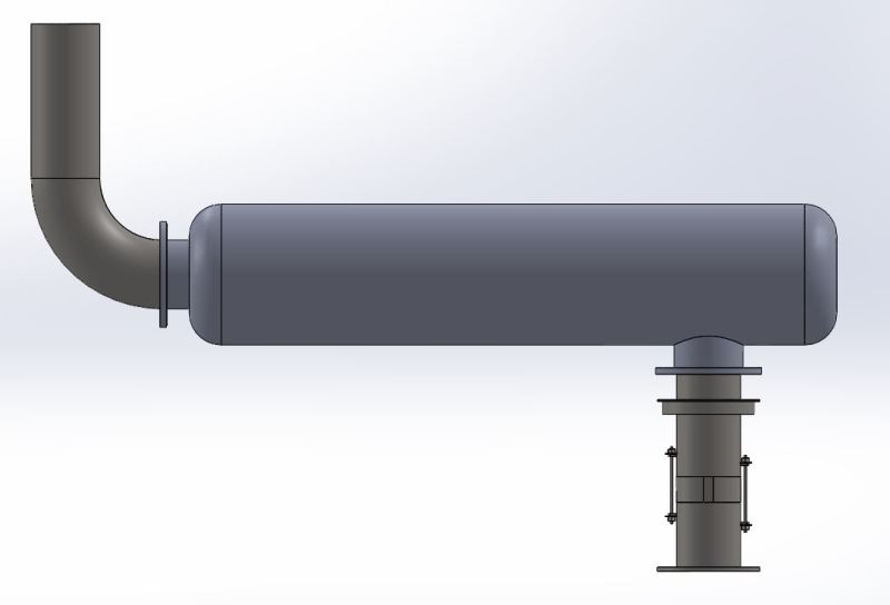
Diesel_Exhaust_ztfwqu.jpg


Here is the information I have:
Exhaust Flow: 4594 CFM (at 6" dia pipe)
Exhaust Temp: 862 F

The manufacturer states that the muffler will have a pressure drop of approx... 8in HG at that CFM.

I'm having trouble relating the data and feel that I am missing some critical pieces. I am some what familiar with Bernoulli's equation.

Any help would be appreciated.

 
Replies continue below

Recommended for you

I'm confused, you already listed an output flow. Do you need it at the exhaust stack exit? If so, you may need temp at that point. If the temperature is nearly the same, you can use your volumetric flow rate and cross sectional area of discharge pipe to get velocity. I have been indirectly involved with similar modeling for gas turbine stacks. We used the temp and pressure at the exit (or immediately prior) to calculate the needed information.
 
So the CFM I listed is at the inlet of the pipe section shown. The inlet is the bottom right connection. The exhaust flows up the first 10" pipe then hits the muffler which is 22" diameter with unknown internals. The only information I was given from the manufacturer was that I will see an 8in HG loss across the muffler. The exhaust then exits the muffler and hits a 10" dia 90 degree elbow and up and out the 10" stack on top.

I've been asked how much velocity is lost through the exhaust. I am assuming flow in is flow out (4594 CFM). Velocity in based on Q=VA would be approx... 97 MPH.

I'll outline some of my questions:
1. Is my assumption of flow correct? If I have 4594 CFM going in I should have 4594 CFM coming out, regardless of what goes on in between.
2. I calculate my inlet velocity at the first 10" dia pipe section as 97 MPH based on Q=VA, is this correct?
3. Is it correct to assume that my velocity will change? I am assuming the velocity will reduce at the 22" dia muffler then increase again at the final 10" stack.
4. My pressures will change based on the pipe size and muffler internals. However will this effect my velocity? or does Q=VA still hold true regardless of pressure.
5. My task came from someone who is assuming that there will be a loss of velocity as exhaust gases pass through the system. How can I determine the loss?
 
Conservation of mass says that mass of air[sub]in[/sub] equals mass of air[sub]out[/sub]. If temperature is constant throughout, then CFM[sub]in[/sub] = CFM[sub]out[/sub]

However, if temperature is NOT constant, then density of air[sub]in[/sub] =/= air[sub]out[/sub]

 
ISTR that a sudden expansion, i.e. fitting a 10" flange to a 6" pipe, will cause a pressure drop. If you have room, a long 6x10 cone would be better, if you are nearing the engine's backpressure limit. Refer to the ASHRAE Handbook if you have it.

Assume the muffler guy's pressure drop number is correct. There is no way to model it without knowledge of the muffler's internals, and even then it's uncertain.

The gas will cool just a little as it travels through the system, but it's probably not worth trying to account for the resulting volume shrinkage, because if the muffler is near anything heat sensitive, e.g. people, someone will eventually insulate the whole system.

Someone may also fit a rain cap to the exit.

Mike Halloran
Pembroke Pines, FL, USA
 
MikeHalloran

You are correct there is a rain cap on the end however I've been told to ignore it for now. I'll explain the 6" to 10" connection briefly to see if your statement still holds. The exhaust starts out as 6" dia pipe then the pipe is fitted with a 10" to 6" reducing flange. Then a 10" flange is bolted to that. So the exhaust comes out of the 6" pipe and is immediately allowed to expand into a 10" dia pipe. I feel like your statement is assuming the opposite where a 10" pipe was feeding a 6" pipe in that case I would agree that back pressure would be an issue.

 
So the exhaust comes out of the 6" pipe and is immediately allowed to expand into a 10" dia pipe.

There ain't no free lunch. See the numbers for a 'sudden expansion' in the ASHRAE book.
Sorry.


Mike Halloran
Pembroke Pines, FL, USA
 
Status
Not open for further replies.

Part and Inventory Search

Sponsor