Continue to Site

Eng-Tips is the largest engineering community on the Internet

Intelligent Work Forums for Engineering Professionals

  • Congratulations KootK on being selected by the Eng-Tips community for having the most helpful posts in the forums last week. Way to Go!

CFS Stud Bracing Confusion

StrEng007

Structural
Aug 22, 2014
506
I found a CFSEI Technical Note that discusses bracing for light gauge studs. One particular section seems to go against the consensus that I've read here.
The generally accepted idea being that, providing sheathing on wall studs would cut down the unbraced length for axial loads.

This is disputed by the note that brings up a topic I haven't seen discussed here before:
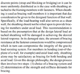

Screenshot 2024-11-08 134115.png

"if the load-bearing wall also serves as a shear wall, the sheathing should not be relied upon to provide bracing for members under axial load."

With that being said, I'm sure that a majority of exterior load bearing walls also serve as shear walls. Also, no matter what direction the MWFRS wind is blowing, you're always going to have either windward, leeward, or side wall pressures. So should we really be designing walls studs as being COMPLETELY UNBRACED for both gravity and lateral loads? How can an exterior load bearing wall ever really be subjected to ONLY bending or axial?
 
Replies continue below

Recommended for you

Yikes. One would think that similar logic would also apply to wood studs.

And it's not as though the non-shear walls in a building actually respect that classification. Stud walls, like me, are notoriously bad listeners.

I suspect we'll have to ignore this unless it surfaces as a hard code requirement that can be enforced.
 
I typically call for discreet bracing of metal studs simply because they're so spindly. With wood studs, you can usually get away with letting them go unbraced during construction. Not so with a lot of metal studs, and so requiring that bracing gives the contractor more flexibility with phasing the sheathing attachment.

Regarding damage at design lateral loads - I suspect this is more a concern with steel studs. When we're talking about gypsum joined to a 0.0625" thick piece of steel with a screw, there's a lot that can happen locally to degrade the connection. A nail shot through plywood into a wood stud? Not so bad. And even if it is damaged, my 'gut' tells me there's a bit more residual capacity in the damaged connection in a wood assembly than in a steel stud with a screw that disengaged or a stud flange that yielded.

I had not heard of that concern, though.
 
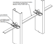
Putting that CFSEI note aside, is it fair to say you agree that bridging as shown below will cut the weak axis compression buckling by half when located at mid wall. It will also do nothing to improve the unbraced length for flexure?

So KL/ry is reduced by 50%, while Lu for flexure remains at the full stud length?

Screenshot 2024-11-08 145704.png


... and then if you're inclined to use the sheathing for something, let it help with Lu?
 
Bridging by itself no, bridging with either end jamb studs or end diagonal/K bracing designed to transfer the force from the bridging into the diaphragm yes.
 
End jamb stud meaning you take the collection of 2% loads and push the summation into the end stud for weak axis bending?
 
Regarding damage at design lateral loads - I suspect this is more a concern with steel studs.

I would like to see some testing on that as my instinct is the reverse.

Based on what I've seen of steel deck seismic testing, I would expect to see some screw plowing through the CFM but no pullout and no outright separation of the fasteners from the studs.

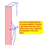
With wood studs, I fear the situation shown below.

If we are to have this shear wall limitation, I would hope that it would eventually take the form of "sheathing may brace studs so long as drift < XXX".

c01.JPG
 
Bridging by itself no, bridging with either end jamb studs or end diagonal/K bracing designed to transfer the force from the bridging into the diaphragm yes.
I'm curious as why Bailey provides load tables for axially loaded studs and specifies the capacities are applicable to walls braced at 4' on center, but doesn't say anything about restraining the bridging at the ends.
 
KootK Said: I suspect we'll have to ignore this unless it surfaces as a hard code requirement that can be enforced.
My belief is that "Technical Notes" are not officially part of the legal requirements of the code. Though good luck arguing that with a plan checker. That being said, there is a good argument to be made that the "standard of practice" doesn't agree with that technical note.

We had a situation in steel design for years where AISC's bracing gurus had been saying for years that the "inflection point" of a beam could not be considered a brace point, but most engineers were doing it anyway. Though, in that case, at least the bracing gurus would point out (in their seminars) why the common engineering practice had never really caused a problem before.
 
I design them assuming they are laterally and torsionally braced at the CRC locations (cold rolled channel) I also design strap bracing for the CRC so they can't all buckle together. I don't count on the sheathing except for non-bearing, interior studs.
 
In simple terms, you use the CRC to reduced your unbraced length for axial loads only?

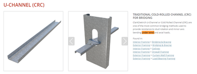
I just don't see how these channels provide LTB for flexure. The image below shows these CRCs brace along the centroid of the cross-section. How would this help the compression flange during wind?

Note: I highlighted the phrase "under wind" to show that even ClarkDietrich agrees these help with, what I assume to be, out-of-plane loads. I'm just not sure why.

Screenshot 2024-11-09 121209.png
 
Apparently there is enough web stiffness to brace the flanges. Honestly, the best way to brace studs is the block and strap method. Block between the studs @ 8 ft. o.c. ish and then add a strap each face and then brace that with diagonal straps I have more confidence in that. Even better if you can get the installer to flip ever other stud so the forces balance out. I have been successful on that on exactly one job.
 
In simple terms, you use the CRC to reduced your unbraced length for axial loads only?

I just don't see how these channels provide LTB for flexure. The image below shows these CRCs brace along the centroid of the cross-section. How would this help the compression flange during wind?

You only need a minor amount of stiffness to prevent LTB, you don't need the that stiffness to act on the flange. If it acts on the web then it still will work to restrain lateral movement of the flange and torsional movement of the section.

As soon as your LTB restraints start to move away from the flanges the analysis becomes much more complicated. But it doesn't mean that the LTB restraints are ineffective. It normally just means it is harder to quantify without extensive calculations of testing.
 
This is a good question. If you are using channel to brace studs in a load-bearing wall application, then I would expect there to also be the clip angle with screws at the connection instead of a spazzer bar or a friction fit type detail. I think that the web would be "reinforced" by the thickness of the clip angle and the continuity of the brace (...again, good point that the channel should be restrained at the ends).

Does it help LTB? Maybe a bit because there is more resistance in the path of torsional rotation and there are now "nodes" along the stud length so the rotation isn't constant along the length. As @human909 says above, it's probably hard to quantify.

Does it help Distortional Buckling, which often governs over LTB? Probably because the web has more resistance (from the clips and the continuity of the channel) to buck out. But...not something I could put numbers to at the moment.
 
I'd expect it to help LTB significantly. Not just "maybe a bit". With the systems we used in Australia this isn't a debated aspect, our codes support it and testing shows it.

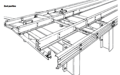
I'm not sure of the various CFS systems that are present in other countries but here in Australia they are ubiquitous in cladding of industrial structures such as factories and warehouses. Likewise bridging is extensively used to prevent LTB. See a typical chart below: At longer spans you need quite a few rows of bridging install to prevent LTB.

1731277665545.png
1731277812453.png
 

Part and Inventory Search

Sponsor