Continue to Site

Eng-Tips is the largest engineering community on the Internet

Intelligent Work Forums for Engineering Professionals

  • Congratulations KootK on being selected by the Eng-Tips community for having the most helpful posts in the forums last week. Way to Go!

challenging problem with pro audio music keyboard (USB) - possibly related to earthing of house

Status
Not open for further replies.

urasoul

Computer
May 8, 2015
7
greetings!

i recently bought a nektar panorama P4 music keyboard and found that the motorised fader on the unit is not functioning correctly.

after speaking with the engineers at the manufacturing group in california, their conclusion was that there is some type of issue with the earthing of my house here (in england), yet they were not able to offer any idea as to what the problem might be. today i received a replacement keyboard from them just to confirm that the keyboard is not faulty and indeed, this new keyboard demonstrates the same problems. i am wondering if anyone here may know more about what the cause of the issues are.


the symptoms:

the unit has 2 usb cables that are to be connected simultaneously. one is for data and to power the keyboard and other powers the motorised fader on the keyboard independently. if i connect both cables to my pc then there are a wide variety of problems with the keyboard's functions (as i recall). if i plug the cable that powers the motorised fader into a powered USB hub and do not connect the other USB cable, then when i run the unit's self test procedure for the motorised fader, the fader functions ok. however, if i connect either of the USB cables to a PC that is connected to the house mains supply then the self-test procedure shows that the motorised fader's 'push' feature is inversed! (that is to say that when i press down on the fader, the keyboard records that the fade is NOT pressed and when i release the fader the keyboard records that the fade IS pressed).


the clue here is that if i plug the keyboard's 2 USB cables into my laptop while the laptop is disconnected from the mains and the ethernet, then the keyboard works fine! if i connect a standard wired ethernet cable to the laptop then the problems arise again.. so it appears that the problem stems from plugging the keyboard into a PC that is in some way connected to the house's earth/ground connection (even via a 3rd unit such as the network router).


what now to find the cause?


i have spoken to the electrical engineer who only recently rewired the house here and he has no suggestion as to what the cause of the issue might be... and since the manufacturer's engineers have no solution either.. i am asking here!
the only thought i have for a next step is to buy an earth testing unit, such as this one on ebay - to see if that sheds any light on the situation.

anyone?

thanks
 
Replies continue below

Recommended for you

Sounds like a ground loop / different grounds problem...

Dan - Owner
Footwell%20Animation%20Tiny.gif
 
Do you have a multi-meter? Check for voltage between all of the receptacles that are related to your equipment. Whenever you have current flowing in a conductor, you have a voltage drop, albeit often very little. There should be no current flowing in the grounding or bonding conductors. If a neutral is inadvertently grounded in the field the current may split between the neutral conductor and the ground conductor. That can cause a voltage drop in the grounding conductor. Another possible cause is a neutral conductor connected to the ground bus in the panel rather than to the neutral bus.

Bill
--------------------
"Why not the best?"
Jimmy Carter
 
thanks for responding here.
i just spoke with the electrical engineer who re-wired our house recently and read him the reply from 'waross' here..
neither of us are exactly clear on what is being suggested by : 'Check for voltage between all of the receptacles that are related to your equipment.'..

and he said that the issue with the neutral and earth connectors is probably not relevant since in england (where our house is) the neutral and earth connectors are always connected back to each other outside of the house / property borderline anyway. (i was not aware of that).

i'm a bit confused by this part of the reply (from above) here - in that this:
' If a neutral is inadvertently grounded in the field the current may split between the neutral conductor and the ground conductor. That can cause a voltage drop in the grounding conductor.'
contradicts this:
'There should be no current flowing in the grounding or bonding conductors. '

doesn't it?

any thoughts are welcomed here.
 
Get an outlet tester that verifies proper neutral and ground wiring, test each outlet by simply plugging it in.
-AK2DM

~~~~~~~~~~~~~~~~~~~~~~~~~~~~~~~~~~
"It's the questions that drive us"
~~~~~~~~~~~~~~~~~~~~~~~~~~~~~~~~~~

 
"i'm a bit confused by this part of the reply (from above) here - in that this:
' If a neutral is inadvertently grounded in the field the current may split between the neutral conductor and the ground conductor. That can cause a voltage drop in the grounding conductor.'
contradicts this:
'There should be no current flowing in the grounding or bonding conductors. '"

No, it doesn't. There should be no current flowing in the ground conductors because the neutral would only be grounded near the breaker. Any grounding of the neutral within the house needs to be corrected.

TTFN
faq731-376
7ofakss

Need help writing a question or understanding a reply? forum1529


Of course I can. I can do anything. I can do absolutely anything. I'm an expert!
There is a homework forum hosted by engineering.com:
 
All the ground points must be at the same potential. There should be no voltage difference between any of the ground terminals between any receptacles.
My explanation may have been clearer;
'There should be no current flowing in the grounding or bonding conductors. Current in ground conductors is a condition to be avoided.

If a neutral is inadvertently grounded in the field the current may split between the neutral conductor and the ground conductor. I am used to industrial applications. By "in the field" I meant downstream of the normal connection between the neutral and ground or in the house wiring.
If there is an inadvertent connection between the neutral and the ground connection in the house wiring then the current may split and part of the current may flow in the ground conductor. This is the condition which should have been avoided.
Thanks for the help IR. The same thing said another way is OK.

Bill
--------------------
"Why not the best?"
Jimmy Carter
 
what was confusing me was the idea that there would be a problematic voltage drop in the ground connection, yet the ground connection is intended to have no voltage.

i just dug out the 'domestic electrical installation certificate' that the 2nd engineer left us (who tested the system) and i can see that in the column marked 'insulation resistance', there are columns marked 'line/neutral', 'line/earth' & 'neutral/earth' - with rows for each set of outlets/sockets in the house. they are all listed at 299 M/ohms. i don't have any test equipment here beyond a basic multi-meter and i'm not sure whether 'insulation resistance' is relevant to this issue or not.

the same certificate shows a value of 30mA for all sockets in the column labelled 'RCD operating current'. (i imagine that some of these figures may be different to american standards as i am located in england/uk.)

other than the possibility of a neutral line being incorrectly connected to the ground line, is there any other possible grounding problem that springs to mind that might cause havoc with some electrical devices (yet leave other devices operating just fine)?
the only idea i have here (beyond having the internal wiring/sockets checked again) is to install a local earth rod into the ground for the whole house, though i'm not 100% clear whether that will help or not. is there maybe a way to create a clean earth connection just for one socket in the house, just to test the theory that the house needs to be more effectively grounded (without going to the trouble of locally grounding the whole house)?

thanks again for the assistance here :)
 
i do have a multi-meter here, yes - though i am not sure what would be beneficial for me to measure.

taking it to a friend's house is the other option, yes. the only reason i haven't already done that is because my home is fairly remote and i don't see that many people here! but i will see if i can find someone tomorrow. ;)
 
Just for the record, there are domestic installations (really quite a lot of them in some parts of the UK - mine is one such) where the Protective Conductor ("Earth Wire", to you and me) is derived within the building by taking a connection off the incoming neutral wire just upstream of the meter.

That said, I doubt that's your problem. If I read your first post correctly, the troubles begin when you make your very first connection to the earth system (I'm assuming that the keyboard isn't directly plugged into the mains, and that things go wrong when you have the laptop on battery, but the network cable plugged in. That to me suggests a bonding issue, rather than earthing. (Bonding is the process by which all accessible extraneous metalwork in the house is meant to be connected together and also to Earth, so that if you accidentally touch a live wire to (say) a water pipe, you don't get fried when you go to turn the tap on).

I think it would be interesting to see what happens if you move the keyboard to some other part of the house - perhaps alternating between laying it down on something that ought to be well bonded to Earth (like a central heating radiator or a stainless steel draining board) and something thoroughly isolated (like a rubber mat in the middle of the room).

I would also be interested in what you see if you connect a digital voltmeter between the earth terminal of one of your sockets and each of the bits of domestic metalwork close to where the keyboard is currently sited.

A.
 
urasoul; Please do some tests. Using the multimeter set to measure mains voltage (250V or more) (make sure the leads are plugged into the correct holes of the meter) and set to AC:

1) Measure between the N and L (as shown on that ebay circuit tester)
You should see approximately 240Vac

2) Measure between the N and E
You should see less than about 2Vac

3) Measure between the L and E
You should see 240Vac

4) Measure between the L and a local ground point. This would be any metal that is well connected to Mother Earth. Examples are a water pipe exiting the ground nearby or if you understand your house plumbing and KNOW that it's all contiguous metal and originates from the earth then any house fixture will do. Beware of disconnecting plastic fixture hook-ups. Alternatively you can take a big screwdriver with a long piece of wire. Strip off a couple of inches of insulation and wrap the stripped part around a long screwdriver shank and tape it. Shove it into the ground somewhere the ground might be a little damp. Water it if needed.
You should see 240Vac

5) Measure between E and the local ground point.
You should see less than 2V preferably 0V


The above tests are primary in nature and show if there is something unusual in the general wiring of your house as related to the specific outlet you're testing.

Let us know what your findings are. Once enough data piles on here, (you've got some nice points already racked up), we'll reach an "ah ha" point and an answer.

Keith Cress
kcress -
 
We are assuming that this is a PME installation with a combined neutral and earth conductor. If it is a remote installation then there's a strong possibility that this is a TT system rather than a TNC-S system.

Can you take a photograph of the electrity meter, consumer unit, and the incoming cable from the utility and post it on here? Do you have the inspection & test sheets from the rewire? One on of the sheets - second one i think - there should be a few tick-boxes for supply sharacteristics. Post a photo of that sheet too. Can you tell if there's an earth rod near the intake? Does your supply come in on an overhead line?
 
'zeusfaber': i have already tested the keyboard in different rooms/areas of the house and different sockets and didn't find any more successful combinations. i'm not clear on why there would be any difference in using the keyboard on an insulated or uninsulated surface, since the keyboard case is made of plastic that, as far as i am aware, is non conductive. what am i missing in your logic here?

itsmoked : thanks for your clear process here. while your advice might be great advice.. i am not so bold with this presently as to stick two wires into the 240v mains socket here based on the advice of someone called 'itsmoked' on an internet forum that i have never met. lol ;)
how would i know that my multi-meter can withstand the voltage/charge? (i only have a relatively cheap multi-meter).

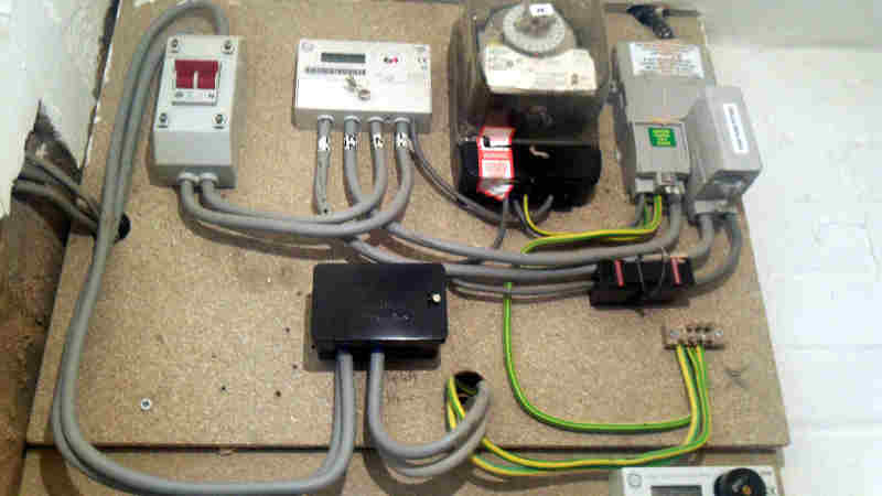
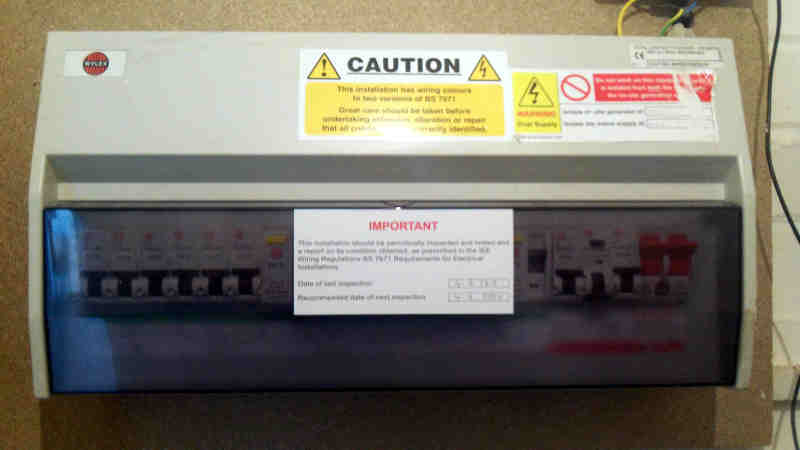
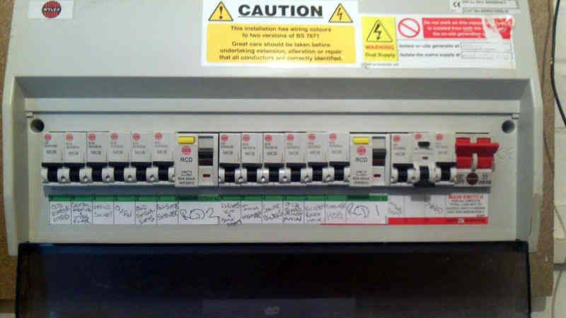
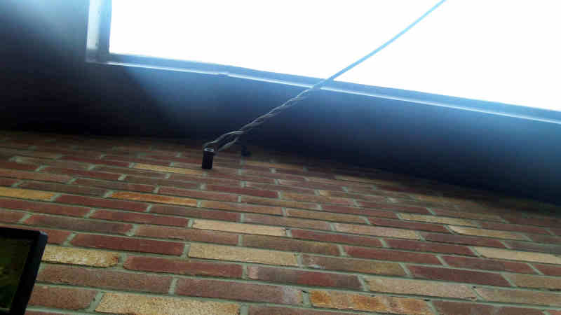
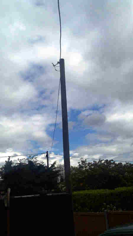
'ScottyUK' : sure, here are the images you have requested. we also have solar panels on the roof, so some of the boxes on the board relate to those. the incoming cable is an overhead one:

board_tpsoem.jpg

fusebox-closed_lamma2.jpg

fusebox-open_ma7gl0.jpg

house-connection_xmnod9.jpg

cable-pole_jgtnyo.jpg


It certainly looks like you have a TNC-S system so you're reliant upon the utility for ensuring that the neutral point of the source is connected to the mass of earth. The neutral and earth share a single conductor up to the service fuse in the grey block at the top right of your installation, and at that point they separate. The neutral/earth conductor is connected to the mass of earth at the utility's transformer, but it's not impossible for the utility's earth connection to be bad. You could consider adding an earth rod or two and connecting them to the earth block on the installation to see if that improves the behaviour of your equipment. If it does make a difference then you need to ask the utility to address the problem with their installation.
 
ok, yes, i think you are correct. so i looked at the small junction block at the bottom-right of the mounting board and see that there is an empty connector there.. is that the spot that i would plug in an earthing rod?
my dad had the idea to connect the earth pin of the plug from one of my computer's psu cables to a grounding point, such as a bare metal area of a radiator pipe in the house, to test the idea of improving the grounding to the computer
- rather than going and buying grounding rods and messing with the main electrical block; does that sound like a wise move here? or is there a reason why a grounding rod or two might give a much better result?
thanks!
 
I'm suggesting that you undertake a trial by improving the connection between your building earthing system - the green & yellow wires - and the mass of earth itself. The only way to do that is using a metallic rod or object buried in the ground. Rods are easy and cheap, but copper mats and cast-iron grids were used in the past. Leave the radiators alone! You have the correct connection point I think - where all the other green & yellow wiring meets. You will need a decent-size cable to the rod.s

 
urasoul said:
i am not so bold with this presently as to stick two wires into the 240v mains socket here based on the advice of someone called 'itsmoked' on an internet forum that i have never met. lol ;)
how would i know that my multi-meter can withstand the voltage/charge?

Well done for keeping your critical faculties switched on! A good way of staying alive (albeit no further forward). For what it's worth (you have no idea who I am either), I think Keith's recommendation is conservative, sensible and relevant.

How do you tell whether your multimeter is safe and suitable for these tests? Since you're in the UK, provided the meter is reasonably new it's quite easy to check: Look at the CE marking on the back. This should be accompanied by a statement like: "According to IEC 61010-1 nnV, Cat nn".

Provided that:

1. The rated Voltage is sufficient (for this job, I'd be looking for 1000V or higher)
2. The category is suitable (either Cat III or Cat IV for these tests).
3. You are using the test leads that came with the instrument, you have had a good look at them and are content that they are undamaged.
4. You have had a good look at the instrument and are content that it is complete (i.e. with all covers fitted), unmodified and undamaged
5. The instrument has either an autoranging ac volts setting, or an ac volts setting of 300V or more.

then you're going to be OK with it.

Where was I going with the suggestion to try moving the unit around? Systems that are connected to earth in only one place are usually pretty resistant to deviations in Earth voltages (at least at normal power frequencies). The problems usually start to show up when you connect different earths in different parts of the system and, since your original post suggested you weren't doing that on purpose, contact through the case looked like a possibility. The question you always have to ask in situations like this is "how does the system know that it's touching a flaky earth?"

Just to add to ScottyUK's comments: In addition to the earthing at the transformer, in a TNC-S system (which is clearly what you have - the photos and the test cert agree), the Utility is obliged to provide lots of additional earthing throughout the local network. If you walk along the street, you will almost certainly find that there's an earthing wire runs down the side of every fourth (or so) pole to make sure this happens. There are a couple of different ways TNC-S (what we used to call PME) systems can get you, so I would suggest you expand Keith's tests a little bit. Do two versions of his Test Five - one measuring between the Earth terminal of one of your sockets and your mains water pipe and one between a socket Earth terminal and a screwdriver stuck into the lawn a few yards away from the house. If you see anything at all between Earth and the water pipe, you need to get your electrician to look at your bonding. If you see more than a couple of volts between Earth and the Lawn, you need to get on to the power distribution company with some urgency.

One other thought. Who are your neighbours? When I lived very close to where I worked, it was relatively common for poorly protected electronics to do strange things - at least until Air Traffic turned out the lights etc and went home for the night.

A.
 
hehe - thanks for confirming. however, the multi-meter i have here is the cheapest of the cheap and has no CE label; plus it also only list cat 1 and 2, not 3 and 4 - so i think i would need to source a new multi-meter to do these tests.
i looked on ebay and found some cat 3 meters for around 50GBP, so i will need to consider the benefits of doing that versus just paying an engineer to come and do it for me.

i just looked at the posts outside the house and the nearest one to our house does have two large-ish black shields running down it into the ground, so i imagine they are the ground connections..
the local area is non industrial and pretty quiet, so i do not sense there are any direct issues of unusually strong electromagnetic activity being involved - though i don't know what's underground.. so that remains an unknown possibility.
 
Status
Not open for further replies.

Part and Inventory Search

Sponsor