Eng-Tips is the largest engineering community on the Internet

Intelligent Work Forums for Engineering Professionals

Changing from DC motor to an AC motor. 2

Status
Not open for further replies.

bsmet95

Mechanical
Aug 16, 2007
114
0
0
US
My understanding of DC motors is very limited. A user has a 30 year-old hoist with a 10HP DC motor. He'd like to change to AC. I've done some research and among other things have noted that torque characteristics are different.

Is there a way to determine an AC motor to use for roughly equivalent performance? The facility has 460VAC and the motor control is DC.

Thanks.
 
Replies continue below

Recommended for you

I'm surprised the electrical guys haven't chimed in yet! [bigsmile] I'll give it a start. You need to find out the speed and torque your current motor puts out. Do you need the same speed/torque characteristics? An AC motor controller can give you lots of options for speed and torque limits.
 
What type of DC motor?
What type of motor control?
What type of hoist?

Bill
--------------------
"Why not the best?"
Jimmy Carter
 
Sorry, guys. I've had to address other issues so I'm late in answering. I'll have to see what info I can get and reply.

Thanks.
 
Disclaimer - I am not a crane drive specialist.

I have only been involved with one of these conversions. It was one of the most tangled, piss-poor jobs I have ever been next to. This was 35 years ago. I may (likely) not remember all. I'll keep the names secret to protect the guilty.

The application was a grapple for moving logs in a pulp mill wood room. The crane DC motor was a 30hp, fairly low RPM - I'm recalling 900rpm. System included a brake and reduction gear to the cable spool. The power source was an MG set mounted on the bridge. The equipment was about 25 years old. Controls and MG set were getting unreliable - more downtime than they could stand. Parts were hard to get - no new part available. When the crane went down, the wood room went down, and a few hours later, the pulp will went down. So it is critical.

The company had just hired this kid (mid thirty's) that is somewhat familiar with the new VFDs that are coming out. "Let's go with an AC motor and a VFD. We will junk the MG set and all the dc controls."

The biggest frame motor that fit in place of the DC is a 50hp, 900rpm. We call GE:
US: Your catalog shows a 50HP, 900rpm, design D. What is the price and availability?
GE: We don't sell them.
US ???
GE: People want to put them on cranes. We don't want the liability​
Yep, that is what I remember him saying.

We go with a Design B, 50hp, 900rpm, and a high-torque AB drive commensurate with the required horsepower. And we hired an engineering outfit that appeared to have creditable knowledge.

Went in right per plan. Control was a nice fighter jet looking stick, forward and back was the winch, L & R was the bridge traverse, buttons for grapple open and close.

First log: Close the grapple. Pick up gently. Move bridge. Operator pulls control clear back to raise quickly. Drive stalls. And the brake doesn't come on cause the control is calling for UP. Operator holds the control back - in fact repeatedly banging the handle back. Grapple drops, cable unspools. &*%$@#%

We fixed the controls so the brake came on any time the VFD stalled. Slowed down the ramp rate on the VFD. And the operators learned to tease the UP control when starting. The motor would handle full up, just not rapid acceleration.

What didn't we do:
As mentioned by Brian, look at the existing motor speed-torque curve. Series DC motors will burn themselves into a molten pile of slag before they quit. The harder they are loaded, they just slow down and the torque goes right up - WAY UP.

Nobody looked at the existing MG set to verify the maximum output. That would have given us some clues about the required peak torque.

Today:
If it is ON-OFF control:
Pick a motor that has sufficient torque at stall to accelerate the load (maybe 2X, maybe 1.5X).
Pick a controller that will stand repeaed jogging duty
If the motor doesn't fit, Get the machinist and welder to work.​

If the crane is big enough that porportional controls are required, consider a VFD sufficient for LRA for a few seconds.

Good luck with your endeavor. Let us know haow it comes out.


Harmless flakes working together can unleash an avalanche of destruction
 
Series DC motor?
Most MG set drives, often called Ward Leonard drives used a shunt motor.
Yes, the motor armature was in series with the generator armature but that doesn't make it a series motor.
With a good control package they were self protecting.
Wound rotor induction motors worked well for cranes.

Bill
--------------------
"Why not the best?"
Jimmy Carter
 
As Bill stated, you can't move forward very far without knowing the nature of your DC motor and drive capabilities.

But as a gross general rule, the advent about 20 years ago of "Flux Vector Control" (FVC) capable AC drives and a feature called "torque proving" was what made it possible to replace DC motors and drives on hoists with AC motors and drives. But be forewarned, not all VFDs are capable of this and some low cost ones will claim capabilities that they don't have. In addition there are plenty of potential pitfalls for the novice. I cut my teeth on them for moving 777 aircraft, so the stakes for mistakes were very very high, but I sat at the foot of a master the entire time. Even if you are not moving multi million dollar aircraft, the risks of dropping a load and hurting someone are still very high, so take that as a precaution; sometimes just because you can doesn't mean you should...

FVC in a VFD means that the VFD will need to take a position feedback from the motor rotor, in the form of a shaft encoder, to calculate the exact vector of flux producing current and torque producing current at the exact moment you need it. Once you have that capability, the drive can make an AC motor produce 100% of it's rated torque at any moment, 150% for (usually) 1 minute, and upward of 250% (Break-Down Torque) for 2-3 seconds if necessary, even at a dead standstill (also referred to as "full torque at zero speed"). That generally gives it the same capabilities as most DC motors.

Torque Proving comes into play when you then apply this concept to a hoist, where there is a mechanical brake involved to hold the load. Because of the possibility of the power failing you can never rely upon a motor and controller to hold a load, so for safety a hoist always has to have a mechanical brake*. So when using a VFD and a mechanical brake, you have to ensure that the motor is putting out sufficient torque even at zero speed so that you can hold the load long enough to set the brake, or keep hold of it without letting it start dropping when you release it. Torque Proving does that. this is not a simple feature to implement though. If you are going to do it, find a supplier that has experienced people to help you.

*On some small hoists that use a worm gear (right angle) drive mechanism, mechanical holding is inherent, so a spring loaded brake is not always necessary.


" We are all here on earth to help others; what on earth the others are here for I don't know." -- W. H. Auden
 
I didn't mean to dis you.
I have worked on quite a few MG set drives.
The largest was four, 1300 HP motors geared together to drive the winding drum in a large dragline.
All shunt motors.
A crane must work at the speed that the operator wants it to run at.
Series motors are great for starting engines but the relationship between the load and the speed makes them unsuitable for cranes.
I have no problem with your post except for your misunderstanding about the type of motor.
And probably the most demanding service is the feedworks in a sawmill.
The motor will be pulling several tons of carriage and log back and forth past the headsaw.
Full forward to full reverse several times a minute.
About 200 HP.
Shunt motor, not series motor.
Full torque at any speed, stepless speed control from forward to reverse.
Good control of the speed.

Bill
--------------------
"Why not the best?"
Jimmy Carter
 
Bill -
You get to say anything you want.
Apparently if I disagree my post gets deleted.
Interesting concept.

Unlike you, I could be in error. That was 35 years ago and I was not the engineer of record.

Just curious - Where were you in 1985 - 1987? This was in Sitka.
We did have a guy named Bill, up from Seattle. He is the one that speced/designed the AC drive/controls. Could that have been you?

carl

Harmless flakes working together can unleash an avalanche of destruction
 
Carl; I had nothing to do with your post being deleted. I was a little surprised to see it gone.
My only issue and it is an indirect issue is with this statement;
iceworm said:
Series DC motors will burn themselves into a molten pile of slag before they quit.
Actually I agree with your statement.
Example; The starter was shot on the generator for a remote mining camp.
It would barely start the diesel when cold and not at all when the starter was hot.
One field coil was so badly grounded that it was disconnected and only one field coil was in use.
We needed the set running and didn't have hours to wait for the starter to get cold.
Three 8D batteries in series for 36 Volts to a 12 Volt series motor and we got the set started.
The next morning, cold, the set started on 12 Volts.
What you said. Rugged as a hammer.
My issue is that your statement seems to imply that a series DC motor was used.
That would not be the case.
Those MG set DC drives were quite common.
They would not drive a series motor.
The motors used are shunt motors.
The shunt field is continually excited with the rated voltage.
The armature is fed a variable and reversible voltage.
Wher do you get the variable voltage? from a DC generator.
How do you control the voltage?
By varying the generator excitation.
The generator armature is directly connected to the motor armature.
Looking at it from a voltage point of view it may be a parallel connection.
Looking at it from a current point of view it may be a series connection.
Looking at it physically it may look like a series connection.
Doesn't matter.
It is a shunt motor.
Where was I in those years?
There was not much work in those years, mostly short term contracts.
Some volunteer work near Lac La Barge, Yukon Territory.
A placer mine in British Columbia. (And the melting down starter.)
An oil re-refinery in Ontario,
Gm Oshawa.
Darlington Neuclear plant.
When PLCs were first on the market, I heard an older engineer complain.
These young guys and PLCs.
They would use a PLC to flush a toilet if they could get away with it.
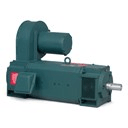
No, I would have tried to upgrade the existing system.
Something like this;
image_vxr77i.png

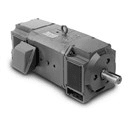
And this for the generator.
image_zn6q6o.png


Bill
--------------------
"Why not the best?"
Jimmy Carter
 
I'd like to throw in what I feel is the distinction here about series DC motors. In parallel ones you can run the armature current into overload and get a proportionate overload torque. In series motors this approach not only overloads the armature it overloads the field. If it wasn't for saturation the torque would go up as the square of the current. This is where they don't stall, they hit the load with an ever increasing torque even if it kills them.

Before power electronics, North American diesel and electric locomotives all used series motors, even most of the AC electrics. The hugely increasing torque at low speeds was exactly the characteristic needed for starting a train and "hoisting" it up a hill.

For cranes however I suspect series is not the right approach. Crane loads don't have near the damping inertia that locomotive loads have. The freeing of a stuck log would lead to split second acceleration in a crane, the operator control would have to have a speed control aspect to it. Cresting a grade in a locomotive with a heavy train behind it however would involve 1-3 minutes for the speed to want to increase so an operator control that just set horsepower and let the series motors trade torque for speed would be okay.

A crane and a locomotive both haul loads upwards. To me the change from shunt to series motors involves where does the hauling weight become low compared to the inertia weight. IE in a vertical crane they are equal, on a 45deg ramp track the haul is 75-80% of the inertia weight, on a horizontal rail track the hauling power is only 3-6% of the inertia weight.

More than Brian's motor speed/torque curve we need the load's (acceleration)speed/torque curve.

Bill
 
Wow. I had stated up front that my DC knowledge was very limited but you all showed me how weak my understanding was. Thank you for your help.

As it was, I consulted a motor manufacturer, who just happened to be the supplier on the original job, and was able to find an AC motor to suit.

Thanks again.
 
When we thing of series motors and torque, the automotive starter comes to mind.
There are a couple of things to keep in mind when considering a starter as a typical series motor.
1. Voltage drop, with a series motor the field current is the same as the armature current.
If the starter was a shunt motor then the field current and the field strength and the available torque would drop as the heavy starting current drops the batteries terminal voltage.
While a shunt starter may perform as well as series starter on a warm day with a new fully charged battery, on a cold day with an old half dead battery the series motor may still start the engine while the shunt motor would not have a chance because of the weakened shunt field.
2. Series DC motors will burn themselves into a molten pile of slag before they quit. Well so will a similar design shunt motor.
Starters fit this category very well. They are designed for a very short duty cycle, measured in seconds. Caution. Do not crank continuously for more than 8 seconds.
3. The starter in your vehicle may not be a series motor.
My 6 liter V8 truck engine starter uses a permanent magnet field. There is no field weakening with a lower battery voltage.
The losses are less. The starter has an internal reduction gear to trade RPM for torque.
This is not new. GM built my old truck in 2001.
Series motors and electric railways
There are two types of electric locomotive.
Straight electric with externally supplied power and diesel electric.
Diesel electric has much more control flexibility that greatly reduces the advantages of series motors.
Maximum torque is limited by saturation. There is not much difference between series and parallel motors as far as maximum torque.
Control. Series locomotive motors used a lot of resistors and tapped fields to give some control of speed. Those resistors were wasting energy. The tap changers were switching full load current.
The diesel electric had control over both the generator and the prime mover. Control could be smooth and efficient by varying the generator excitation and the prime mover speed.
Transpositions could be used with either motors. eg 6 in series, 2 x 3 in series, 3 x 2 in series and 6 in parallel.


Bill
--------------------
"Why not the best?"
Jimmy Carter
 
Bill R, I would like to comment on your points a bit. I mainly mentioned locomotives to contrast that while series motors don't seem to have much value in industrial use they do have lots in railroad applications.

A major difference in rail traction applications compared to industrial ones is that the available horsepower stays level over 9/10ths of the speed range, IE at 1/10th speed, 10x torque is available, continuously. Even with a series to parallel transition of motor connections the series motor's natural trade off of speed and torque avoids the extra control equipment that would be needed to run a shunt motor's field from overload at start down to weakened field at speed. That's the opposite voltage change to what's needed on the armature so connecting them in series was a natural.

Diesel electrics -all of the American builders used series motors up until AC drives. The throttle chooses levels of engine revs/maximum fuel (thus HP), the motors' torque/speed tradeoff inherently takes care of correctly dividing that HP to rail speed & torque, thus the volts/amps. The generator excitation is controlled by the governor to adjust those volts up to load but not overload the engine's output. The latter point prevents the motors from stalling the engine which had been an unacceptable problem until 1914 when a gent by the name of Hermann Lemp at GE sorted it out. The only variable resistor in the scheme is in the field of the generator's exciter. Applying shunt motors here would have meant separate field control equipment to get the needed speed range.

External power DC locomotives -were an extremely small part of North American mainline railroad history. The resistive losses were minor as they only occurred during speed changes, the locomotive engineer always sought one of the series or parallel motor connections for sustained running. This is also true for the huge number of streetcars, they tended to alternate power on one of the direct notches mixed with coasting to sustain the required speed. Again this is where the large inertia/momentum of a train comes in. I haven't heard of any case where shunt motors were used in North American DC traction.

External power AC locomotives -indeed used tap changing but the motors were still series because of the torque/speed range.

Thanks for the ear, Bill
 
Back to cranes
Switching hoist motors from DC to AC vector control, or actually from any other hoist arrangement (wound rotor, Ward Lenard MG set, etc) requires first redoing all of the motor sizing calculations, and then making sure you drive has ample torque to accelerate your proof test weight. But remember to set the drive acceleration slow enough that their is not a risk of acceleration generated fatigue failures.

If you hoist spends significant time at low speed make sure that the motor builder knows what you are doing, as there are additional measures needed to get rid of the heat.

Make sure your chosen hoist drive is rated for hoisting applications.

Don't skimp in the hoist breaking resistor. All of the energy used to hoist the load winds up in the resistor when lowering.

Torque proving - I think all hoist rated drives do this now. It is essentially doing math on the vector power going into the motor to determine the amount and direction of output torque. If torque is equal to or greater than the criteria set in the drive parameters then the drive releases the mechanical brake.
Fred
 
Thankyou keith

FORGOT ONE - AC drives can brickwall - something that never was a problem with old technology. Old tech, available torque follows the motor torque - speed curve.
With AC motor drives, the available torque = drive torque setting. Does not matter what the motor by itself can do.

As long as the I^t protection is set within motor limits, short time torque bumps to 400% (drive max amps or max torque parameter) might be OK, but not on a hoist, you never want to risk loosing load control. When I was purchasing cranes for my employer the CMAA specifications for cranes did not address this quirk of solid state drives in their guidance.

With a hoist, minimum available torque must exceed proof load weight + drive train friction + minimum acceleration rate to ensure load control.
Fred
 
Status
Not open for further replies.
Back
Top