Continue to Site

Eng-Tips is the largest engineering community on the Internet

Intelligent Work Forums for Engineering Professionals

  • Congratulations waross on being selected by the Eng-Tips community for having the most helpful posts in the forums last week. Way to Go!

Channel beam deflection with varying cross section

Status
Not open for further replies.

DansailV

Student
Oct 24, 2021
3
Hi all,

I am new on this forum. Im a mechanical engineering masters student.

For an assignment, I am designing an overhanging beam, and optimizing it for weight.
Due to production and material choices, we went with U (channel section) beam.

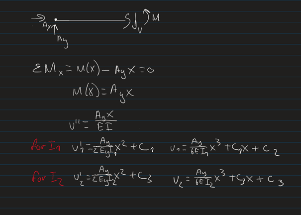
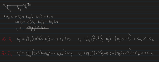
To minimize weight, I want to vary the cross section along the beam. To approximate this, I have subdivided the beam into three sections with a different cross section thus different moment of inertia, see pictures. I was getting along with the calculations, but now have 8 constants to solve for and only 6 (7 if v3=0 is counted) boundary conditions. Im also hesitant about how I set up my calculations in terms of Inertia for the second cut.

Could anyone point me in the right direction as to how to proceed?
Thanks in advance

Thanks in advance.
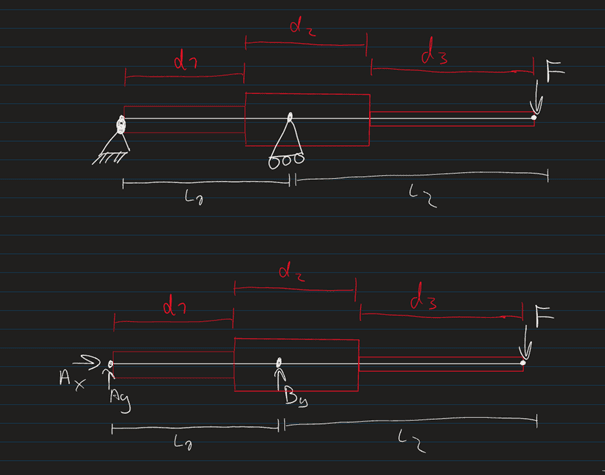
Afbeelding1_m1qlc0.png
Afbeelding2_ravnh2.png
Afbeelding3_lnvtjy.png
Afbeelding4_qn8n3u.png
 
Replies continue below

Recommended for you

Unless you are doing something much more complex than a quick look suggests then Ax=0, from an FBD

Ay, and By are directly calculable by taking moments and equilibrium, since your system is statically determinant

Therefore you can write your shear force graph
Then you can integrate that to give your BM diagram

And after that it's just Macaulay's method , presumably with 4 sections to it.


Cheers

Greg Locock


New here? Try reading these, they might help FAQ731-376
 
Dear Greg,

Thanks for the lightning fast reply.

I should have clarified, I have already calculated reaction forces and constructed my shear and moment graph. I was now trying to implement the three different cross sections.

That said, I will take a look at macaulay's method, thanks!
 
Macaulays method will give you the correct result, but it's easy to make a mistake along the way. I don't know which methods you have been taught in class, but I would use the area-moment method. The Conjugate Beam Method is similar and is also good. Check them both out.

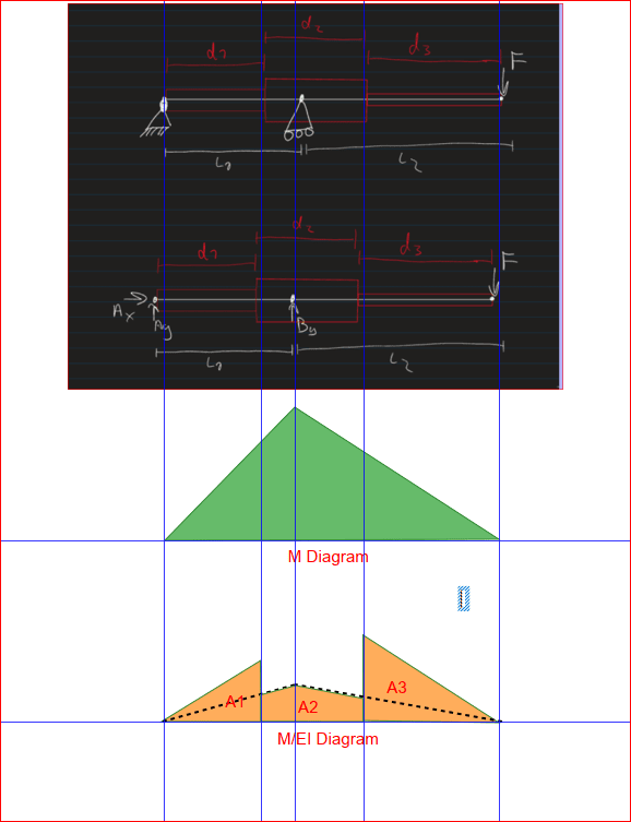
Capture_ndbfra.png


If your only applied load is the force F at the end of the cantilever, M[sub]B[/sub] = F*L2 and varies linearly to zero at points A and C (where C is the end of the cantilever). You will need the M/EI diagram to find slopes and deflections. The M/EI diagram looks like the M diagram, but is divided by a variable EI, in your case, three different values, so the M/EI diagram will have discontinuities at each change in EI. If E is constant throughout, only the I value changes.

You can see three areas in the M/EI diagram, marked A1, A2 and A3. Each area can be calculated, knowing the shape of the M diagram. Each area represents the change in slope from left to right. The black dashed line simply shows how the ordinates of area A2 can be calculated.

The change in slope from the tangent at Point A to the tangent at Point C is A1 + A2 + A3. Deflections may be determined, knowing that the equivalent angle change in the section of beam marked A1 is the area of A1 and occurs at the c.g. of A1. And the same for A2 and A3.


BA
 
Hi,

I just wanted to thank everyone for the quick and interesting responses.
For now, I used 4 discrete cross sectional shapes instead of four. This resulted in 8 equations, so my system of 8 unknowns could be solved.

I will look into the other methods proposed on this forum out of interest still. Thanks

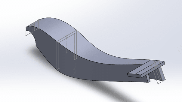
It is a brake pedal.

oh and Desertfox, we were not allowed to use FEM on this assignment and the material was a CFRP composite so a castellated beam would be suboptimal and rather complex to calculate in this particular situation. Here's a screenshot of what the optimized cross-sectional shape of the composite part of the pedal looks like now.

cfrpsheetiso_u7vgfj.png
 
That looks like an interesting project. If you could express EI as a continuous function, it would be possible to express M/EI as a continuous expression which could be integrated from end to end.

BA
 
Hi DansailV

I didn't mention FEM.the castellated beam was just a means of reducing the weight of the beam but keeping the beam cross section constant however now you have told us what the beam is for I can see it wouldn't be suitable[smile]

“Do not worry about your problems with mathematics, I assure you mine are far greater.” Albert Einstein
 
If a straight line variation is used for EI, from maximum at support B to 0 at points A and C, then M/EI is constant for the full length, which should make it easy to analyze. Of course, it is not possible to have an EI value of 0, so a minimum value would need to be introduced at each end, in order to resist shear.

EDIT: Or, since a specially fabricated shape is contemplated, make the elastic Section Modulus S, linearly variable so that maximum fiber stress is constant throughout the length of beam.

BA
 
Status
Not open for further replies.

Part and Inventory Search

Sponsor