Continue to Site

Eng-Tips is the largest engineering community on the Internet

Intelligent Work Forums for Engineering Professionals

  • Congratulations KootK on being selected by the Eng-Tips community for having the most helpful posts in the forums last week. Way to Go!

Channels reinf in wide flanges 1

Status
Not open for further replies.

BAGW

Structural
Jul 15, 2015
388
Hi All,

I have come across a situation where channels are welded to the web of the wide flange to reinforce the existing beam. This detail is on existing drawings and its a building that was built in 1980's. The beam is a roof purlin supporting deck and snow. Seems like it was reinforced as it was over-stressed by 15%. Maybe beam was reinforced as shown below because of site condition. I cant say why exactly.

I am re-evaluating the capacity of the composite section and I need some inputs. All members are A36 steel. I am using ASIC 360-13th edition and seems like the sections are compact. I am using section F2 to evaluate the capacity and there is around 30% increase in capacity with channel reinforcement compared to W8X10 steel alone. Is using section F2 the correct way of doing it? Also how do I calculate the weld required between the channel and the wide flange? As the CG of channel and the composite section are at the same location the equation VQ/I goes to zero.
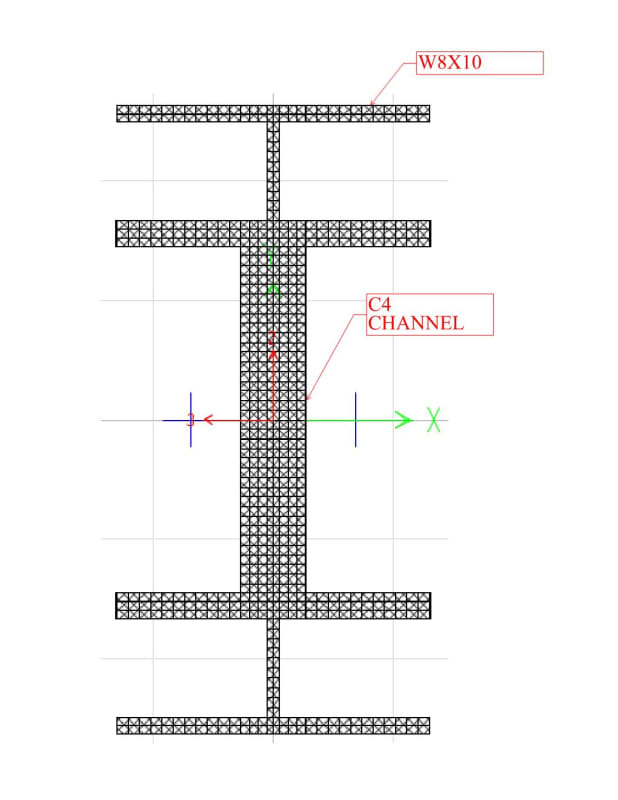
Document1_ed4bpg.jpg
 
Replies continue below

Recommended for you

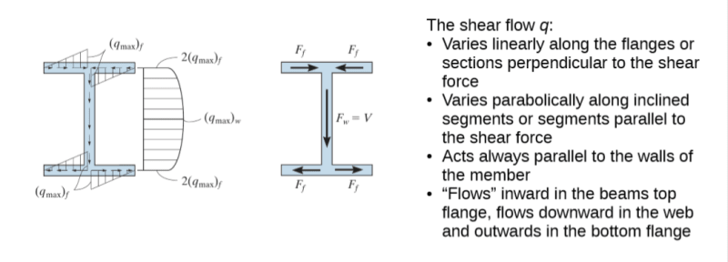
Note, at the NA, the shear flow is maximum. See the linked paper for details. Link
 
WARose - there is no shear flow in this configuration at those welds.

This is a classic case of simple deformational compatibility.

There IS shear flow in the web of the WF beam at the point of the welds, as there is for any beam that bends.

But the Q value for each channel is 0...thus there's no shear flow.
(The area of the channel - that which you are connecting, is located a distance of zero from the NA, thus Q = 0 and shear across the weld is zero.)

Look over WillisV's response in this thread (about half way down) thread507-168270
...where he states the same thing.

Think of it like this:
1. The main WF takes load and tries to bend down.
2. Now imagine that the two channels have, instead of rigid connecting welds, a multitude of little connecting bolts in teflon-coated horizontal slots connecting the channels to the beam that cause all three sections to bend down with the same vertical deflection.
3. These theoretical vertical-only fasteners, can only take vertical load.
4. Since the connections are vertical-only, there can be no lateral sliding force transferred between them.
5. If there's no sliding force, or "need" for the two shapes to move relative to each other (there isn't) then there's no horizontal shear force.
6. The channels will bend downward, with the WF, and have the same deflected shape across the span, despite there being no horizontal mechanism (with the theoretical horiz. slots) to transfer shear.
7. The only thing transferred is the vertical force between the WF and channels. The three each are "pushing upward" in resistance to the load.
8. The deflected arc length of the curved channel flanges, and the deflected arc length of the WF web located directly at those flanges, is exactly the same.
9. If the arc lengths are the same (with the slotted hole fasteners) then by Hooke's Law you have the same strain along the three shapes at that point
10. If the strain is the same, there is no difference in relative movements between points along that arc and therefore no horizontal shear occurs.

Horizontal shear flow is only when you have a depth difference in the built-up shape where the upper portion wants to move a different amount than a "lower" portion.
Thus Q is calculated based on the area "above" or "below" the connection point relative to the combined NA.


JAE is correct. Shear flow q must be continuous, unless the channels and the beam web can be glued together, which is not possible.
 
But the Q value for each channel is 0...thus there's no shear flow.
(The area of the channel - that which you are connecting, is located a distance of zero from the NA, thus Q = 0 and shear across the weld is zero.)

But it's not for the upper part of that beam. If the 3 pieces are going to act together (with a combined "I")....there will have to be shear flow.
 
Yes - the shear "flow" is all vertical. Not horizontal.

Here's an article on "flitch" beams which are similar to this case in that you have multiple members side-by-side.
Note that there is no mention of VQ/I for horizontal shear flow.

You are simply sharing load vertically.

Shear flow can be imagined like this - you bend a thick phone book such that the pages slide along each other.
Each page is above, or below, the other such that the arc lengths are different. This is horizontal shear.

Now turn the phone book 90 degrees as though each page is side-by-side and bend the phone book about an axis perpendicular to the pages.
The pages all bend and there is no sliding between each other. Each page has the same strain at similar points up and down the vertical depth....no horizontal shear.
 
The channel web and the beam web, though in contact, are two separate surfaces, thus represent a discontinuity that the shear flow in beam web cannot jumped over the channel web.
 
I might add that if the channels were offset from the NA just a bit, then there would be horizontal shear.

 
Here's an article on "flitch" beams which are similar to this case in that you have multiple members side-by-side.
Note that there is no mention of VQ/I for horizontal shear flow.

I'm not following what they are doing. They do say at one point: Rational Method: The required bolt size and spacing is determined from structural calculations. (Which they don't present.) That says to me there is a alternative to what they present here.

But in any case, I don't see much difference between the example I gave and what the OP is after. So we'll have to agree to disagree on this.
 
WARose - about to say the same thing. Take care.

 
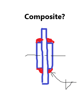
I don't think that's the key. The question is the 3 plates built-up shown below composite or not? If yes, shear flow is present, as the flow path is from the middle plate through welds to the side plates, the flow paths are all continuous. If not, then shear flow is only present in the middle plate, shear flow at the side plates are zero due to discontinuity.

f_nqasta.png


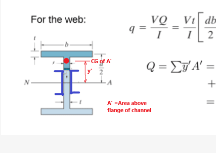
w_x2avxk.png
 
Under this situation, a designer shall ensure the continuous flow path by weld the channels to the beam web, then assume full composite action exists. The strength of each weld, fw, is equal to V*(A'*y')/Ic, which is shear flow intensity at the beam web - channel flange junction. Parameters A', y' are as shown on the graph below, and Ic is the composite moment of inertia calculated by SRE.

Note, after sizing the weld, it shall be double checked by strength requirement, fw ≥ √(fa[sup]2[/sup]+fv[sup]2[/sup]+fb[sup]2[/sup]).

w_law5lg.png
 
Status
Not open for further replies.

Part and Inventory Search

Sponsor