Continue to Site

Eng-Tips is the largest engineering community on the Internet

Intelligent Work Forums for Engineering Professionals

  • Congratulations SSS148 on being selected by the Eng-Tips community for having the most helpful posts in the forums last week. Way to Go!

Check for flange to web weld of plated section

Status
Not open for further replies.

ChrisToms

Structural
Sep 6, 2011
4
Hi all steel experts there..


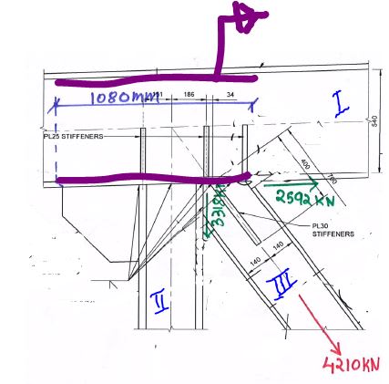
Below shown is connection for truss.
My primary objective is to check the adequacy of weld (in purple)
Member I is top chord of truss, II vertical and II diagonal truss member.
We have shear force on member I at the location of connection, say 300kN (this will include the contribution from diagonal as well since the shear is extracted from global analysis line model)

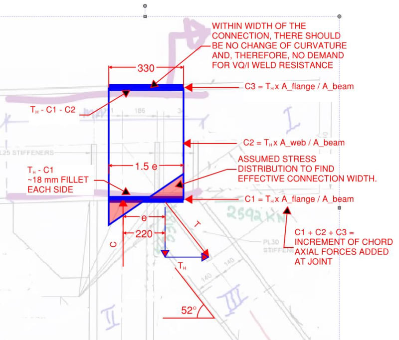
My question is, for a plated section we normally check the shear stress (VQ/Ib) at the weld location and check if the weld is able to carry that.
But in this case, do we need to consider the local force flow, that is, the axial force on diagonal is 4210kN and is the horizontal component of this force to be added with force contributed by longitudinal shear stress?
weld_nazatc.jpg
 
Replies continue below

Recommended for you

I'd say your primary question is more how you're getting the load out of the brace first. The misaligned vertical stiffener, and no horizontal stiffener. Looks all wrong to me.

Look into the uniform force method for proportioning the forces out of the brace. This will give you both shear and tension for the weld design. I'd say it's pretty safe to superimpose these with the shear flow. Alternatively if you know the web plate is good for the load, simply weld it to develop the full capacity of the web plate may be sufficient, so many butt welds so what's one more at the web between friends.

But like I said the whole thing looks a bit suspect to me.
 
1) Interesting problem. I can't say that I've ever seen anybody specifically address this aspect of truss connection design. I assume that the top chord is a built up member (plated as you say).

2) As you've rightly identified, you've got two sources of demand on these welds.

a) Any VQ/It demand associated with curvature change in the chord. A handy feature of this, I would argue, is that the chord can't really change curvature over the width of the connection owing to the restraint provided by the connection. So I think that it's reasonable to assume that there is no VQ/It demand over the width of the connection and that this demand need not be combined with the local demand source associated with the local force transfer coming in from the truss webs.

b) The demand associated with the truss joint introducing a new increment of axial force into the chord. Note that we assume that this increment is concentric with the chord which means that it has to be concentric when it leaves the portion of the chord considered to be part of the joint. In my mind, this means that we need to to distribute the force increment across the chord section within the width of the joint rather than letting it distribute out into the flange/web welds beyond the joint. I don't doubt that such a redistribution is possible but it would be inconsistent with the story that we're telling about a concentric joint that doesn't introduce substantial moments into the chord.

3) In my opinion, the hardest part about this is deciding what the effective width of the joint should be. I've made a suggestion below that I feel is reasonable but I'm certainly open to other suggestions.

The sketch below summarizes this and is drawing showing only the chord axial force increment introduced by the truss joint. I'm getting a required, two sided fillet weld of 18 mm. Substantial. And probably fairly conservative based on my estimate of connection width. Obviously, you'd want to ensure that the web itself can handle this level of load. Whatever your VQ/It demand might be at this location, it's probably a drop in the bucket relative to the local demand and, so, probably not a big deal to double up.

c01_qrv8cb.jpg
 
ChrisToms, if I were you, I'd design a connection of this kind with a gusset plate similar to the left stiffener.
As for now I don't understand what will carry the huge componens of tension in the brace and transfer them further to the post and the chord.
I don't know what is the code that you use, but the Eurocode states, that one should carry out independent checks for both force componenets in bracing while checking the gusset plate.
You're solving a minor problem with welds of the chord, while the major one is with the brace itself (IMHO).
As I understand, you're trying to make a nominally pinned connection of the brace, but to my view, it's better use a gusset plate and to consider it as a rigid connection in the global analysis (and include the moment component conservatively) even if your connection will actually be semi-rigid.
 
Status
Not open for further replies.

Part and Inventory Search

Sponsor