Continue to Site

Eng-Tips is the largest engineering community on the Internet

Intelligent Work Forums for Engineering Professionals

  • Congratulations SSS148 on being selected by the Eng-Tips community for having the most helpful posts in the forums last week. Way to Go!

check the capacity of a steel angle

Status
Not open for further replies.

jseng9

Structural
Oct 27, 2017
53
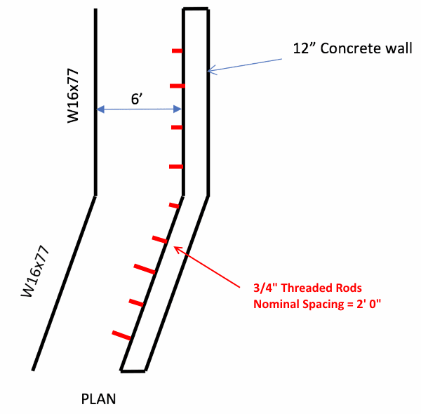
I need to check the capacity of an L3xL3x1/4” angle supported by (3/4”) diameter bolts embedded 3-3/4” into a concrete wall spaced 24” on center to support the edge of slab of a parking deck. The bolts are epoxied with HILTI RE 500 v3 epoxy. The angle is supporting 6’ tributary width of slab. Loads I need to account for are 4.25” concrete on 2” metal deck + 25 PSF SDL + 40 PSF LL.

I’m very new to steel design and don’t have experience with design of angles or connections. Some things I think I need to account for are: flexure of the angle, yielding of the bolt hole, shear of the bolt, pull out from the concrete. The issue is I have never checked any of these things before and would really appreciate it if someone would be able to walk me through the steps or point me to references for checking these things.
 
Replies continue below

Recommended for you

I won't try to check the stresses, but I have a question that anyone might ask. If the angle is attached to an upward pointing leg, will anyone ever have to replace or tighten the anchor bolts? Also If it is placed with the attached leg going down,I'd expect some local yielding of the angle at each bolt, but how much?
 
Sketch your problem with two views (section and plan view at a minimum): I "think" I understand the geometry, but am not sure.
 
I'd not do any calculations for this poster. When any one of us designs something doesn't first select the stuff that goes there, but we first come up with forces involved to then decide what goes there by going to our references to select the sizes of the components. You don't pick what looks to be maybe OK and then see if you guessed right. That's a basic process that the poster forgot. With experience some designers have done certain steps so many times they do not need to do this process for every detail. That's how's come they can do it for lower price with confidence. In some cases they can skip the design and use a larger item knowing, by experience, that it works. However this poster is not experienced and must go through all steps. We might assist with details, but that's not designing it for them.
 
Hi all, thank you very much for the responses. Just to clarify, this is an existing structure that I am checking based on field measurements and contract documents. I have attached photos (section and plan) showing the configuration. If anyone could help me verify if I am on the right track in terms of the limit states I nee to check, suggest any additional limit states, and provide guidance on how to check the limit states I would really appreciate it.
 
 https://files.engineering.com/getfile.aspx?folder=d2b0bb88-3d2a-4217-be57-5539c26cbe0e&file=Screen_Shot_2018-10-04_at_9.55.59_PM.png
Just to clarify based on the above questions: Yes I am checking for bolts and not threaded rods. SDL is superimposed dead load (25 PSF) the other applied loads are 4.25" on 2" metal deck = 6.25" concrete... (150 PCF*6.25"/12 = 78 PSF)+40 PSF DL. Total DL = 103 psf... total LL = 40 PSF. I have not checked for impact loading before. This is a parking garage, would you need to check for impact loading?
 
Just to repeat: We don't do the engineering calculations for you. Is this job in cold climate, wet, drainage? Any salt de-icing involved? Age? Corrosion? What is the general condition of the support as well as the slab? How deep is the actual depth of the anchors? Any deflection noted, angle, bolts, etc.?
 
However your fasteners are connected to the concrete, I'd design for shear only since the rigidity of the slab dictates the loading will essentially be shear.

Dik
 
jseng9 - Explain or show how bolts (with heads) are epoxied in the wall.

Will try to guide you though the checking "process". You will do all the calcs, not me.

I have designed, built (construction management), and used equivalent installations... but for much heavier loads.

Note: You will be checking more than the steel angle. The complete assembly (steel angle, bolts, epoxy anchoring) has to be satisfactory.
A clue: The steel angle is probably the least of the concerns.

[idea]
[r2d2]
 
Is the steel deck in your sketch drawn correctly? If so, it is spanning parallel with your steel angle, so your angle will see very little load.

Another load to consider - the angle might be transferring lateral loads (diaphragm to shear wall) as well.
 
Thank you SlideRuleEra - to install the "bolts" the contractor drilled an over-sized hole in the concrete wall, cleaned the holes, injected the Hilti epoxy and then installed the "bolt" into the wall. I was mistaken when I said "bolt". It is acually a 3/4" diameter threaded rod. The angle was fastened to the rod using a steel washer and hexagonal nut. I am happy to do the calculations myself... your guidance would be much appreciated.
 
Per the other question from CanPro... The steel deck is actually spanning the direction I indicated. Thanks, I didn't think about the lateral loads. We are using steel braced frames and there is a brace very close to this wall so I would think that would take most of the lateral loads.
 
Is that "brace" actually a long span joist (truss)? Does it deflect even slightly under loads?
 
SlideRuleEra said:
1) Bolts or threaded rods?
2) Explain or show how bolts (with heads) are epoxied in the wall.

jseng9 said:
1) Yes I am checking for bolts and not threaded rods.
2) I was mistaken when I said "bolt". It is actually a 3/4" diameter threaded rod.

Lesson #1: "The devil is in the details". If I had not pursued questioning on this subject there would be little chance of making a meaningful analysis. As my high school math teacher always said, "You must be exact". [smile]

Back to business. You will need the allowable shear and tension loading on 3/4" bolts embedded 3 3/4" in concrete, with the specified Hilti product. Compressive strength of the concrete may be needed to obtain those values. Do you have that information? You don't need to tell us the "values", just that you have them. If you don't have them, get them.

[idea]
[r2d2]
 
jseng: Have to be careful... hilti oversize is only 1/8"

Dik
 
Thanks for the questions, its teaching me to be more specific and detail oriented. SlideRuleEra I do have the allowable shear and tension values for the 3/4" threaded rods embedded in the concrete from my Hilti catalog. oldestguy the brace is a wide flange rolled section.
 
jseng9 - Good. I assume the threaded rods are installed per this marked up sketch. Is so, do two things:

1) Get confirmation from the field on bolt spacing. When installing epoxy anchors it is common for the drill to hit existing rebar and the hole has to be relocated. If there are spacing variations (in the field), determine maximum bolt spacing.

2) Determine the tributary loading area of the slab for one bolt, with maximum bolt spacing. Either sketch it or tell us (in detail) what it is (to verify that you have it right). When selecting maximum bolt spacing, consider how the last bolts are installed at the ends of the angle(s)... this could be the worst case.

TR_Spacing-1_fhyihe.png


[idea]
[r2d2]
 
To expand a bit on SRE's point #2 above - look for splices in the angle. If the last anchor in a run of angle is located too far from the splice, you get the angle effectively cantilevering past the last anchor, which will increase your effective tributary area.

Also, if you can, maybe post a more complete plan view of what is going on. As I mentioned above, and you confirmed, the deck is spanning parallel with the steel angle, so the tributary width of the angle is not 1/2*6'.
 
Status
Not open for further replies.

Part and Inventory Search

Sponsor