Continue to Site

Eng-Tips is the largest engineering community on the Internet

Intelligent Work Forums for Engineering Professionals

  • Congratulations SSS148 on being selected by the Eng-Tips community for having the most helpful posts in the forums last week. Way to Go!

check the capacity of a steel angle

Status
Not open for further replies.

jseng9

Structural
Oct 27, 2017
53
I need to check the capacity of an L3xL3x1/4” angle supported by (3/4”) diameter bolts embedded 3-3/4” into a concrete wall spaced 24” on center to support the edge of slab of a parking deck. The bolts are epoxied with HILTI RE 500 v3 epoxy. The angle is supporting 6’ tributary width of slab. Loads I need to account for are 4.25” concrete on 2” metal deck + 25 PSF SDL + 40 PSF LL.

I’m very new to steel design and don’t have experience with design of angles or connections. Some things I think I need to account for are: flexure of the angle, yielding of the bolt hole, shear of the bolt, pull out from the concrete. The issue is I have never checked any of these things before and would really appreciate it if someone would be able to walk me through the steps or point me to references for checking these things.
 
Replies continue below

Recommended for you

Slide Rule Era: My bet is the WF sections are not parallel to the wall unless they also carry beams at 90 degrees to the wall.
 
I don't get it. What is supporting the steel deck? It's flutes run parallel to the wall but there are no beams shown to support the deck. If there are beams running perpendicular to the wall, the connection of beam to wall is the important consideration, not the support of the edge of the deck.

It makes more sense that the flutes of the deck are perpendicular to the wall.

BA
 
jseng9 - [wink] Don't read the following:

Spoiler: Per comments earlier in this thread about not helping the OP with calcs, I'm perfectly willing to let the OP make "mistakes" in defining the tributary area (as part of the learning process). IMHO, when that sketch / description appears we will be able to ask how steel deck orientation affects the tributary area for a threaded rod.

[idea]
[r2d2]
 
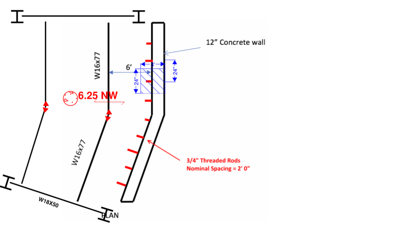
SlideRuleEra Here's my sketch! Red arrow shows span of deck over steel beam. Blue hatched region is what I believe to be the area of slab supported by one threaded rod. Horizontal dimension of trib area is 3' vertical dimension is 24".

To answer questions asking for a larger section of plan see this image. Beams are moment connected in the middle.

P.S. The original design called for a beam running parallel to the wall and supported by the columns but it was not installed because it conflicted with the wall... then the angle was installed to support the deck.

revised_sketch_2_pedn1t.png
 
A 6 foot span in a parking garage "might" be limited to 40 psf live load, but you need to verify that this is not in ANY area where a car/truck/forklift/construction lift vehicle will drive over that section of the concrete. A car or forklift will not generate 40 psf live load, but four 6 inch square 9 1/4 sq foot) loads (that are moving) in four different places, each wheel with car_weight/4 (truck_weight_4/4) on each 1/4 sq foot. yes, the whole pattern is spread out, but the actual loads are concentrated at small areas. Probably with the the two axles in lines perpendicular to the wall.

A pedestrian walkway is different - that would be a spread out load.
 
jseng9 - Ok, sounds like the steel deck flutes are oriented perpendicular to the wall. I agree with your tributary area.

1) Calculate the total load on that one threaded rod. What is it and how did you get it?

2) The slab bears on the 4" outstanding leg of the angle. Determine how you would apply that load to the outstanding leg. I can think of at least four ways, all make some sense, some are "better" than others. Tell us what you recommend and why.

[idea]
[r2d2]
 
Here is another example of bad instructions for how to post. It takes 26 postings to finally get around (and maybe net even then)to knowing what the full question is. So sit back and let's see ALL of the possible things that may possibly affect this question. I was beginning to think this was a trick question or by a non-engineer since the poster was using terms not usually associated with what is there. For instance what is the "brace"?
 
Hi Oldestguy, I'm an engineer in training. Sorry if the question wasn't asked as clearly as possible. I thought I was given lots of specifics. The brace is a lateral brace. It is a W12x40 brace but its north of this area. Calculated loads in the threaded rod are attached. I think the load would be applied as a line load, it's unrealistic for the slab load to be applied as point loads, I can't think of any other way this load would be applied. racookpe1978 the deck is supporting vehicle live loads. Is it not acceptable to model the deck as uniformly loaded? It was designed using Risa3d as a uniform live load... would you have to do some type of transient design for all of the possible axle loads? How would you recommend doing this?

 
 https://files.engineering.com/getfile.aspx?folder=97b4e80f-91cf-4341-86a9-6939e6b0de49&file=calc2.png
Okay, you were really helpful. I think the review needs to be focused on checking the angle. All of the additional things that people have brought up have been helpful but that's not really the focus of my post. I was looking to figure out how to check an angle anchored in a wall supporting a slab.
 
The AASHTO bridge design spec has extensive information on calculating the distribution of wheel loads on concrete decks, but the most prominent factor is how close to the wall do you consider that a wheel load can get? If there is the potential for a tire to be 1 foot away from the wall, most of that wheel load will be on a single anchor. Even if the angle is stiff and strong enough to distribute the load to several anchors, it's still going to be significantly more than 290 lbs. So when someone parks their 4 ton pickup next to the wall, what do you foresee happening to that 3/4" bar embedded 3-3/4" into the wall?
 
Thanks for the helpful suggestion Hotrod10. I will look into AASHTO and reconsider my applied load to be the weight of an appropriate axle load acting over the tire area.
 
HotRod10 makes a very good point about wheel loads ending up close to an anchor.

Another point to consider is potential corrosion. If the structure is in an area which sees winter snow, it is probable that salt is being used on the roads. This means that vehicles will be tracking road salt into the building which will result in corrosion of any exposed metal parts, including the angle and its fasteners.

It may be prudent to check the tributary area for dead load as you have done, but to take the worst case possible for live load. Also, you might want to give some thought to protecting all exposed steel against corrosion. Personally, I would have concerns about using exposed steel beams and metal deck in an environment such as that.

BA
 
Status
Not open for further replies.

Part and Inventory Search

Sponsor