Continue to Site

Eng-Tips is the largest engineering community on the Internet

Intelligent Work Forums for Engineering Professionals

  • Congratulations SSS148 on being selected by the Eng-Tips community for having the most helpful posts in the forums last week. Way to Go!

Checking Tower Crane Lateral Support Connections

Status
Not open for further replies.

RobertHale

Structural
Jan 4, 2007
163
I have received the submittal for the tower cranes of a 22 story flat-slab building. As expected, the manufacturer has identified a couple of locations where the crane will need to be tied to the building for lateral support. In addition to placing the lateral forces in my slab, the manufacturer is also specifying a 1-foot vertical standoff for the connection plates (for a total eccentricity of 1'- 6 1/2". This is outside my wheelhouse, and I want to make sure I am checking all the failure modes and that my methodology is reasonable.

I am going to/have checked the following failure modes: concrete bearing failure of the through-bolt sleeves, concrete breakout of the connection, two-way "punching" shear at the anchorages. I am checking the bolts but not the connecting plate assembly (I am going to put a CYA note on the submittal about it.) I think the checks of the bearing failure and two-way shear are straight forward out of ACI. The concrete breakout has me scratching my head. The one person in my office that has checked this condition for this type of structural system used the Hilti Profis software and ACI App. D to derive a breakout value, but App D specifically precludes conditions with through bolts. The only step I have from there is to apply the cracking strength of the concrete (either 7.5 root f'c or 5 root f'c) to an assumed breakout surface. I have used this method with a 35-degree angle similar to the App. D assumptions. It worries me that this capacity is so much higher than the capacity predicted by App D.

Finally, The height offset is proving difficult to resolve. Initially, I thought that the through bolts and the sleeves would cantilever and the offset would be little more than a shim, but the sleeves fail miserably as cantilevers. For a concrete solution, the interface needs to be reinforced to transfer the 340kip of ultimate shear acting concurrently with 520 kip-ft of moment. The required reinforcing just to satisfy shear friction makes a chunk of concrete extremely impractical to serve this purpose. The only thing I can think of is to provide a steel plate "chair" fabrication to transfer the shear first to the "chair" then from the "chair" into the slab using the bolts. I have checked the specified bolts for the combined tension and shear force using AISC, and it works, but I am not even sure if that is the appropriate code to use for the design of elements like this.

My questions for everybody:
[ol 1]
[li]Is there another check I am completely missing?[/li]
[li]Is the approach to breakout reasonable, and what angle and tensile capacity would you use?[/li]
[li]Any other methods to achieving the offset?[/li]
[/ol]

I would appreciate your thoughts on this and any nuggets of wisdom you may have discovered checking these types of items in your work. Thanks in advance for the help with this.

Robert Hale, PE
 
Replies continue below

Recommended for you

Can you sketch up what this looks like? I'm not fully getting it, I don't think.
 
I have a number of thoughts but you're not bound to like 'em.

- In general, I think that you've got your bases covered with regard to the checks that you're doing with one possible exception. I believe that you should also check your slab for the bidirectional moment likely to be induced at the anchorage. That, particularly, given that are punching shear provisions assume that complementary and competent bending reinforcement is provided where punching shear is checked. Insufficient slab flexural capacity = bunk punching shear capacity. The University of Michigan tested this out for us a while back creating a rather large kerfuffle. Probably just means some concentrated top and bottom steel at the anchorage locations. No biggie.

- It worries me that you seem to be evaluating punching shear for the slab moments concurrently with breakout for the shear parallel to the slab. There's got to be some manner of interaction between those two failure modes as there would be if you were doing App D stuff. Especially if you need to crack out the concrete breakout frustum a bit before engaging supplementary rebar.

- I pretty much refuse to through bolt nowadays for serious loads. That, simply, because there is no accepted design procedure for evaluating through bolt connections that I am aware of. All I know of is this: Link. Given how terribly wrong we all seemed to be about anchorage pre-App D, I find the notion that we could somehow "first principle" our way through something like this to be very suspect.

- While I often hear of engineers using shear friction to help with concrete breakout situation, I'm not a believer. Firstly, the load is predominantly perpendicular to the shear plane rather than parallel to it. Secondly, I believe that slip along the shear plane would put your SF reinforcing in compression which is a no no per ACI 318-14 R22.9.4.3. Lastly, you'd have to crack the concrete in order to engage the shear friction reinforcement. That might not go over so well with the owner.

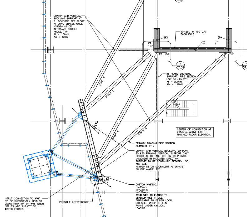
- Like your chair idea, you may want to construct something of your own that distributes the anchorage loads to your slab in a more favorable manner. The sketch below shows a rather extreme solution for a steel framed building where it was decided to bypass the deck slab altogether and attach to the shear walls directly. That would be much too extreme for your situation of course.

Capture_v0upok.png


I like to debate structural engineering theory -- a lot. If I challenge you on something, know that I'm doing so because I respect your opinion enough to either change it or adopt it.
 
Disclaimer: I've never actually heard of anyone doing this. It's got some mechanical curb appeal though.

Capture_xy5bjw.png


I like to debate structural engineering theory -- a lot. If I challenge you on something, know that I'm doing so because I respect your opinion enough to either change it or adopt it.
 
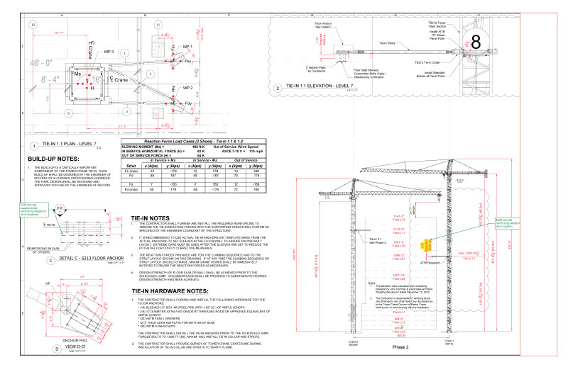
TLHS: Here is a page from the submittal with the configuration indicated. I think the only issue with their drawings is the Detail C doesn't properly reflect the condition with the slab and the 1-foot fill. I will also note that my slab is 8" thick and is post-tensioned.
TowerCraneConnection_kplmvy.jpg

KootK:
- I am going to throw the induced moment into my floor plate model and see what additional reinforcing I need to add to get slab to resolve the moments. I completely neglected to mention that in the OP.
- I am a little confused about your second statement. Did you mean not concurrently considering the breakout and eccentricity induced moment? I honestly had not thought to combined the two. Now that you raise the interaction issue, you are right there should be some interaction effect, but there is no guidance on how to account for it unless I just use the App D. interactions. Two things occurred to me in regards to this on the drive home. (1) It might be worth it to use the plane concrete chapter and evaluate the surface of the "shear failure cone" for the combined tension from the induced moment and the breakout tension. I was just going to evaluate a polygon offset from the "chair" structure plus half the slab depth. (2) Err on the conservative side and provide enough localized reinforcing to develop the entire shear "tension".
- I agree that trough bolting seems an abyss of nothingness. I am worried that once I say "through bolting is not acceptable" the manufacturer will throw responsibility for everything after the connecting strut back on me. I know they have a mountain of previous applications using this method, and I am loath to "poke the bear" as it were.
- I was only thinking of applying the shear friction provisions for the cold joint between the top of my slab and the 1'-0" required offset shown in Detail 2, assuming the offsetting material is concrete.
You sketch is effectively what I am planning with the Chair. I am just going to use the 8 Connecting bolts/rods.


Robert Hale, PE
 
Agree re bear poking. I'm okay with others through bolting so long as they're taking responsibility for it. In fact, I welcome the opportunity to review their calc methodology.

I was thinking of something else on the shear friction front. Consider my previous comment redacted.

I like to debate structural engineering theory -- a lot. If I challenge you on something, know that I'm doing so because I respect your opinion enough to either change it or adopt it.
 
RobertHale:
They may need the added 1' elev. separation for crane settlement and movement, out at the edge of the bldg. That doesn’t mean you need that much vert. clearance 10'-15' inside the bldg., where you likely have a pinned connection. You probably need the 6.5" of height to physically clear their strut termination shape/size, but you don’t need the extra 1' to the pin center, thus a smaller ‘e’. This would significantly lower the moments on the slab and terminal structure. Have you talked this over with them? Yes, someone has to design a fairly elaborate shoe or terminal structure of some sort to take fairly large lateral loads down into a slab system which was never intended to take these concentrated loads. And, you know your slab and structure better than anyone else, so you should certainly define these limits, and be involved at this level. I wish you had posted that crane plan sheet as a pdf, so I could enlarge it and actually see what’s there. At the two locations for the shoe or terminal structure you might cast 8 or 10 steel pipes into the slab. There length would match the slab thickness, and their i.d. would fit a 1 or 1.25" dia. through bolt. These pipe locations can be measured to drill a weld pl. which fits atop the slab and takes the welding from the shoe or terminal structure.
 
dhengr:
Here is a link to the Tower Crane Submittal Sheet. They are specifying the offset due to the curtain wall configuration (I spoke with them yesterday morning). I read the drawings as needing 1'-0" to the base of the strut connection plate and then there is an additional 6-1/2" of eccentricity in the connection plate (I confirmed the eccentricity this morning with the manufacturer.) They are specifying pipes for 1-1/2" through anchor rods. According to the engineer at the manufacturer, they just specified the largest bolts the connecting plate could handle. I am going to check the rods with a critical eye now that they said they basically did not design them for the loads.

Robert Hale, PE
 
RobertHale:
These days, it makes your ass tired how many extra responsibilities and duties are pushed back on the EOR who likely never even imagined that these things or the time involved would fall in his lap. Can you check into the curtain wall situation in that bldg. bay and leave a few pieces of their framing out until later when the final glass installation takes place. This might allow you to eliminate the need for the extra 1' of strut elevation at the shoe or terminal structure.

I would want to know a lot more about their shoe or terminal structure “S213 Floor Anchor.” It seems to me to be a hunk of junk which most good engineers would have considerable trouble justifying. Assuming 1.5 - 1.75" thk. t&b horiz. pin pls. and .75 - 1" side pls., about 2'-8" long and 10.5" high, just my best guess from proportions of the small details, and looong 1.5" dia. bolts, I’d look at the following. The long bolts canti. 2.5" out of the slab/sleeve to the bot. pin pl. and they transmit the strut loads, in shear and bending to the slab? The 6.5" eccentricity shown in their det. “C”, and the moment it induces is reacted by the side pls. on the conc. slab. There must be some hellishly high bearing stresses on the conc. when you combine moment and bolt tension reactions. In addition, what are the deflections and bending stresses in the top horiz. pin pl. when you start tightening the through bolts. I think I would take a W10x, or some such, with 1" horiz. t&b bearing pls. under the shoe or terminal structure to make up the 12" ht. they claim they need, if you can’t get that reduced. Their shoe side pls. would be welded to the top horiz. pl. and there would be some appropriate stiff. pls. btwn. the t&b pls. and the WF. I would extend the WF into the bldg., maybe on the line of the main struts, with a 1" bot. bearing pl. on its inner end. Could you embed some pls. or angles in the slab, missing your reinforcing, to weld this WF to, so as to get the shear loads into the slab?
 
Status
Not open for further replies.

Part and Inventory Search

Sponsor