Continue to Site

Eng-Tips is the largest engineering community on the Internet

Intelligent Work Forums for Engineering Professionals

  • Congratulations SSS148 on being selected by the Eng-Tips community for having the most helpful posts in the forums last week. Way to Go!

Checking Welds

Status
Not open for further replies.

Whoopdedo_LSU

Structural
Apr 27, 2017
35
I have a question involving welding. I am welded a 4x3 member to a 6x3 member. I cannot get a weld to work. From testing, it was found that we can only get 1/8" weld penetration from the groove weld. I am wondering if I can add a "stiffener" in to get extra weld length.

Capture_rqssqc.jpg


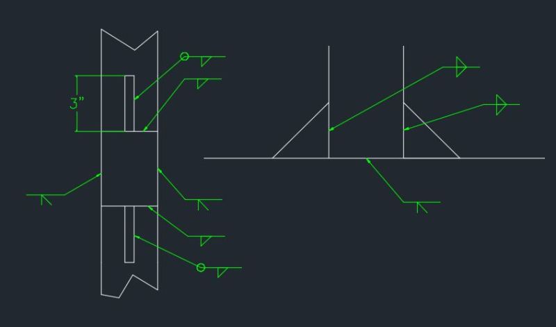
The left is a plan view and the right is elevation.

If I can use this extra weld length from the stiffener, how would I treat that added weld area?
 
Replies continue below

Recommended for you

What types of loads are you resisting at the joint? Stiffeners tend to marginally effective in these applications because you wind up trying to push axial and bending load through the most flexible parts of the tube members (the walls in flexure). If it would be aesthetically acceptable to weld gusset plates to the sides of the tubes, that would make for a much more robust connection.

I like to debate structural engineering theory -- a lot. If I challenge you on something, know that I'm doing so because I respect your opinion enough to either change it or adopt it.
 
You should be able to fully develop the HSS4x3 with fillet welds all around, but you will have to reinforce the wall of the HSS6x3 if the smaller member has axial load or bending.

BA
 
I also recommend gussets(as KootK suggested) on the side of the members....I usually ignore the capacity of welds across the face of tubular members in a case like this because of the much greater stiffeness of the sides....
 
What's your situation with the groove weld on the sides? That weld symbol doesn't actually make sense, because whatever it is is a combination with a flare bevel weld that isn't indicated.

Are you actually cutting a bevel into the vertical member and combining it with a flare bevel weld like the callout is sort of indicating? Is what you're actually doing a flare bevel weld without a cut bevel where you leave the vertical member with a square cut end and fill the gap with weld material. Either way, those are both prequalified as partial joint penetration welds with maximum achievable strengths equal to the lesser of 60% of the vertical (in your first view) wall, or 100% of the horizontal wall that has the radius. This is per Canadian code (CSA W59), but the American one is pretty comparable.

If you wanted a full penetration weld, you would have to get enough gap that you can combine the flare bevel weld with a butt weld, complete with a backing bar.

Diagrams are sourced from the prequalified weld tables in W59

pjp_g4ieyd.png


Alternately, you could weld a plate in between so that you can flare and then reinforce with a fillet weld, but then you're going to stick out the sides a bit.

This is why thinking through joints is a big deal when sizing HSS members. Certain arrangements can be significantly harder to connect than others. The most flexible way to allow easy connections is to have members that frame in be a size skinnier than the member being framed to. It gives you way more options on connections. Equal sized members can be good and straightforward to connect if you can eat the loss in strength inherent with the easy welds.

Think about whether you actually need a full strength weld along that edge of the member, though. You normally don't.

I'm not really answering the question asked, but I think the above is kind of at the root of the issue that got you here.

I agree that if you're in this situation now, the best resolution is either butt weld, sticking a plate in between the two members, or welding a pair of guessets either on the faces of the members if you can, or inset maybe 8mm clear from where the radius flattens out so that you can fillet it, as long as you can get the capacity you need there without a punching failure.
 
These are extruded aluminum members. Not HSS. There is no radius on these members.

Baretired- how could I say I'm getting a 4 sided fillet? Maybe explanation above changes that?

I'm trying to avoid adding a plate that extends out. This has to be flush (1/8 in) from another existing surface.
 
Yes, the above explanation changes that. Please ignore my earlier remark.

BA
 
Kootk- I'm resisting a lot of weak axis moment. My structure is trying to act as a truss system even though I don't want it to. Think of a bleacher system that is supported every 16ft. Its trying to act as a truss and transfer moments at the ends (supported sides). I'd rather just a bracing system but it won't work like that. It's acting like a truss bridge.
 
TLHS-as I just mentioned, I'm not using HSS. I'm using extruded aluminum members. I was planning on beveling the 4x3 down to a knife point and welding to the 6x3. I'm worried that the penetration will be as small as the tests we've done which resulted in 1/8in throat of bevel weld. The penetration varies with the welding procedure and how it's best to weld aluminum members together in this application.
 
Whoopdedo_LSU:
Don’t forget that allowable stresses are reduced in the regions of welds, when welding most aluminums. Also, since you don’t indicate any loads or moments or the extrusion thicknesses, it seems reasonable to assume very low stresses, D.L’s. only? Keeping the important design details and info. secret always leads to better solutions. You might cut bevels in the two vert. sides of the 3x4 tube, and weld them full and flush to the two sides of the 3x6 tube. You could extend the lengths of these welds by adding triangular stiffeners similar to what you show, but four of them, out at the side walls. Cut bevels on both square edges of these stiffeners, essentially as continuations of the bevels on the 3x4 tube. You can improve these a bit by radiusing the 45̊edges/sides, a quarter circle radius, this softens the stiffener stiffness near the terminations of the bevel welds. Then, just use a fillet on the top and bot. of the 3x4 tube to the 3x6 tube, but only 2 or 2.5" long, don’t run these welds right into the corners out at the stiffeners and side walls, this causes a nasty triaxial stress condition with the welds in those corners.
 
I would expect even an extruded member would have some type of radius at the corners...but since there is a "strip-tease" type of info-flow on this problem...I expect more will be revealed.........
 
SAIL3- I didn't think it necessary to provide all information since the original question was just involving adding stiffeners to get more weld area. Just wondering if it can be done and how would you treat it.
 
Even if it's aluminum, I don't see why you couldn't do a combination butt/groove weld with a gap and backer to get full joint penetration. Strength disparity between the weld area and normal base metal will depend on the alloy.

I'm not a weld engineer, but it's weird to me that you can't get more than an 1/8th of an inch of penetration with a properly prepared groove weld, even without a butt weld in there. How thick is the wall of your tube?

Unless you can figure out your weld issue, I'm back to saying that the way to go is two gussets on each side, 8mm from the edge so you can fit a 6mm fillet in there easily. Then double check that you don't have a punching issue.
 
Status
Not open for further replies.

Part and Inventory Search

Sponsor