Continue to Site

Eng-Tips is the largest engineering community on the Internet

Intelligent Work Forums for Engineering Professionals

  • Congratulations waross on being selected by the Eng-Tips community for having the most helpful posts in the forums last week. Way to Go!

Chip self contact in 2D orthogonal cutting

Status
Not open for further replies.

VaggelisKas

Industrial
May 11, 2015
36
Hello community,

I have the following simulation problem.
I an trying to simulate a case of 2D orthogonal cutting.
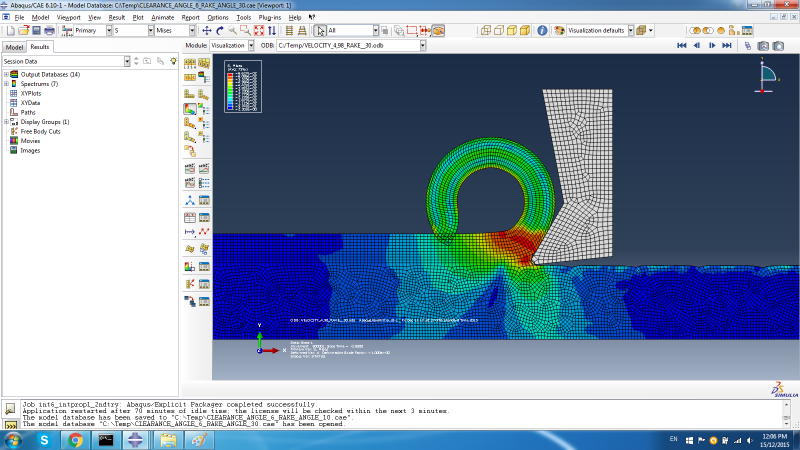
The chip is normally created but when it curls up there is no interaction between the surfaces.
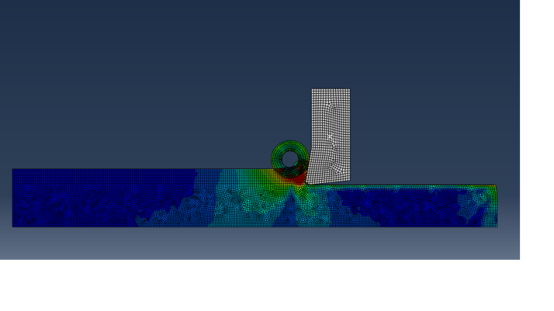
24rtf24_azjpil.png


I have tried to use the self contact on the outermost surface of the workpiece but I get the error of the extreme deformation of
the elements.
Any ideas would be highly appreciated.


Thanks in advance.
 
Replies continue below

Recommended for you

Hi,
Have you created a element surface set of the internal element faces and added it to the general contact? If not, maybe it could help.
 
Hello and thank you for your answer.
The general contact algorithm does not work at all for a 2D simulation.
The contact algorithm I use for this problem is a surface-to-surface contact with the master surface defined as the faces of the tool
that come in contact with the workpiece and a slave node based surface defined as the chip.
Any more help would be highly appreciated.
 
I still have not come up with any solutions.
Anyone has any ideas about how I can model it correctly?
 
If you share the input file or .cae, maybe I or someone else can have a look.
 
Thank you for your answer.
What I am trying to do is as follows:
In order to simulate a correct 2D orthogonal cutting process I need to create a contact between these surfaces :
24fgg2f_ifyzqu.png

and this:
wefcw2er_ydmzqz.png

which are on the same body.
I have implemented a self contact algorithm about the first surface, but then, when the chip is curled, two more surfaces need to be have a contact property:
this one
tgb3rfewv_fvc16g.png

comes into contact with this
24fgg2f_ifyzqu.png

The only contact I have used is a surface to surface contact that is as follows:
24f242ecf_nchvjd.png

The result I get is:
jgfgt_x4pzj9.png

My goal is to stop the elements on the tip of the chip to penetrate one another.
Can you tell me a correct way to implement these contacts?
I attach the .cae file.
If you need any more clarifications please let me know.
Thanks in advance.
 
Hi,
By adding "self contact" to the top face and the face closest to the cutting tool, the contact you wish can be obtained.

I did have to change the mesh in order to get it working (not a nice mesh). It still looks a bit funny. I guess shear causes a strip of the cutting-curl to split. I think you are on the right track!

How confident are you in the material parameters?

Cheers!
 
 http://files.engineering.com/getfile.aspx?folder=3e2ab62d-5e4f-408d-9731-b5d03b54483f&file=contact.inp
Thank you very much for your effort!
I had that strip of metal on my model as well...in order to fix it there needs to be a more dense mesh below the chip area.
My material parameters are taken from a material library.
What kind of elements and meshing technique did you use?
 
Hi,
No particular mesh technique. I basically made the mesh finer at the area where the tool first make contact with the work piece.
I used the same elements as you. The element library for this model felt a bit limited.
You might want to make the mesh quite a lot denser. Elements close to the cutting tool tip were stretched quite a lot before failing.

All details is in the previously attached input file. Note that the mesh was not nice (limited resources).

Too bad general contact don't work for 2D. I have done similar test models in 3D and it was a lot easier if I remember correctly.

Best regards,
 
The self contact of the faces you mention does the trick for the given step time.
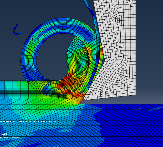
But if I change the velocity BC and give a higher value and the curl goes further this happens:
Untitled6_ulfmol.png

That is proof that the simulation still needs something.
If you or somebody else has any more ideas as to how I can define the contact between these surfaces in 2D I would be very grateful.
24fgg2f_gxwmce.png

wefcw2er_bn7yr1.png


Once again, thank you very much for your effort and advice.
 
Maybe it it easier to extrude it to one row of 3D elements and use general contact.
 
Hello community,

I tried a new approach to the problem.
In this model, my workpiece is a combination of 2 parts (workpiece-chip) bound together by a tie constraint.
Moreover, a new wire based part is created and placed on top of the chip via a tie constraint.
Below you can see the assembly without the chip part.
Untitled15_tygdgf.png

The interactions I have now are as follows:
a surface-to-surface int for the tool-chip
a surface-to-surface int for the tool-wire
a surface-to-surface int for the chip-wire
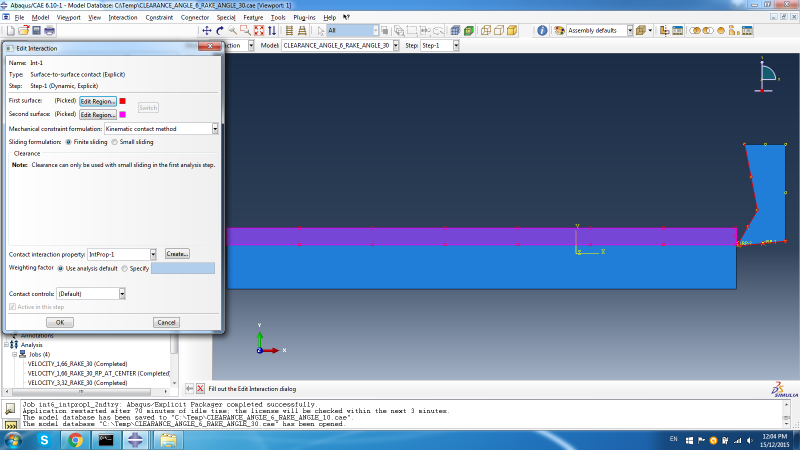
The simulation runs, but for a very big value of the clearance in the final interaction window.
If someone has any idea I upload the .inp file file for references.

Any kind of help would be highly appreciated.
 
Status
Not open for further replies.

Part and Inventory Search

Sponsor