Continue to Site

Eng-Tips is the largest engineering community on the Internet

Intelligent Work Forums for Engineering Professionals

  • Congratulations KootK on being selected by the Eng-Tips community for having the most helpful posts in the forums last week. Way to Go!

Chord Shortening of a plate when subjected to pressure 1

Status
Not open for further replies.

GoncaloPT

Structural
Jun 9, 2020
24
Hello!

I'm having some troubles, and I really don't know if i'm over complicating. Hopefully some of you will be able to help me.
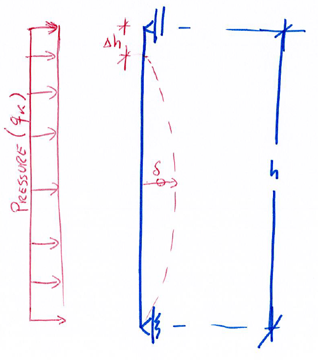
I'm currently trying to prepare some hand formulas to put on my excel sheet to evaluate the chord shortening of a glass panel when subjected to wind pressure.
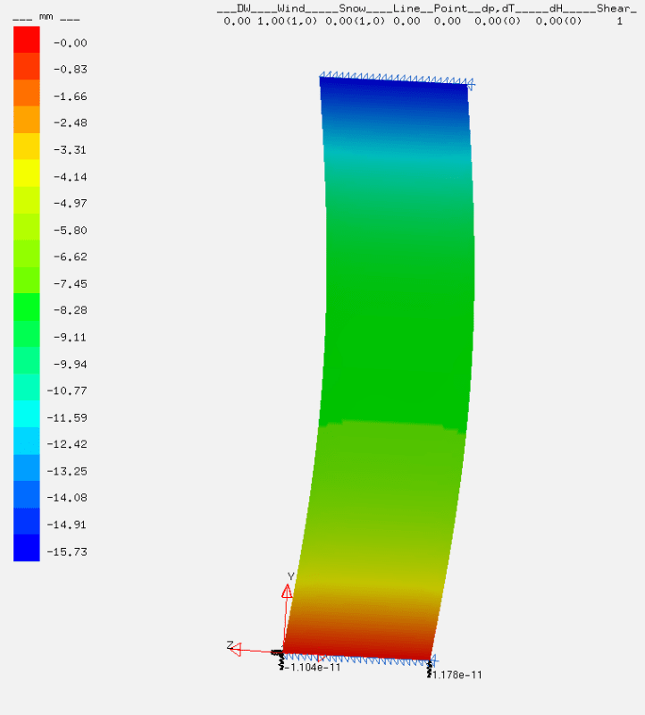
I'm able to find the deflection (δ on the scheme bellow) on the pane and I would like to backward evaluate the Δh (vertical displacement) in order to ensure the glass ply doesn't slip out of the framework.
image_kp3kkh.png


Vertical Displacement on a FEA
image_ezk6gb.png

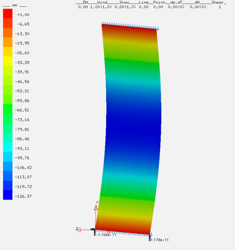
Horizontal Displacement on a FEA
image_z38c67.png
 
Replies continue below

Recommended for you

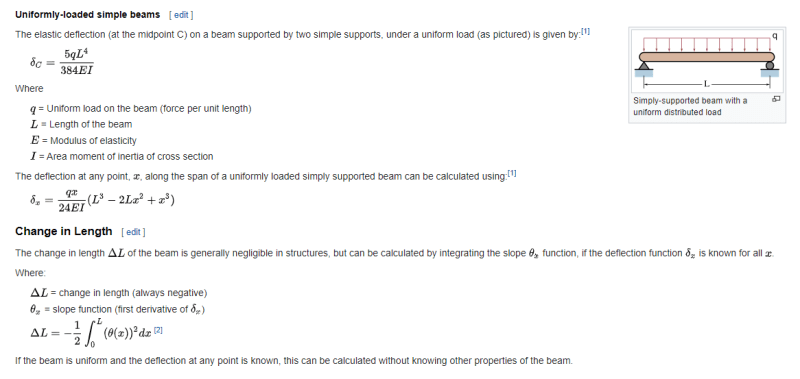
See if this helps (excerpted from Wikipedia).

d_usv5gf.png
 
Do the results from the FEA shown reflect the actual condition, or are they just to check the calculations? I only ask because 126mm (approx. 5") of horizontal deflection is pretty significant. For a condition with the height width ratio shown, supporting glass top and bottom only, I would be way more concerned about the horizontal deflection than the vertical shortening.
 
Does the FEA assume the window is a plate, or does it allow membrane forces.

For the horizontal "shortening" I'd assume an arc, length L (the original width of the window), with a depth, d, 126mm

So the semi-angle of the arc is theta = L/2/R (radians)
and cos_theta = (R-d)/R
solve to R and theta
and shortening is L - 2*R*sin_theta

126mm does sound like a lot … what's the width of the pane ? >2m ?

another day in paradise, or is paradise one day closer ?
 
In the past, I`ve oversimplified RB's procedure and considered it to be two right triangles. Their method is probably more precise, if you can figure out the radius, but my math is easier.
I (also) assume the length is constant (2* hypotenuse), we know the length of the short leg of the right triangle (the overall horizontal deflection), and then solve for the long leg of the triangle.
The last time I did this was for a hundred foot long railroad bridge, and I was shocked at how little shortening was predicted at the ends based on deflection at the middle.

Alternatively, I've also done a guess and check solution in CAD. It's an arc with three points. Guess at the vertical movement, check our overall member length, and then adjust the vertical movement until you hone in on an answer.
 
@retired13 with the change in length formular for beams, considering a beam with a 1000 mm x 10mm (I=8.33 cm4) and L=2500mm i got a delta L of -17.016 mm.

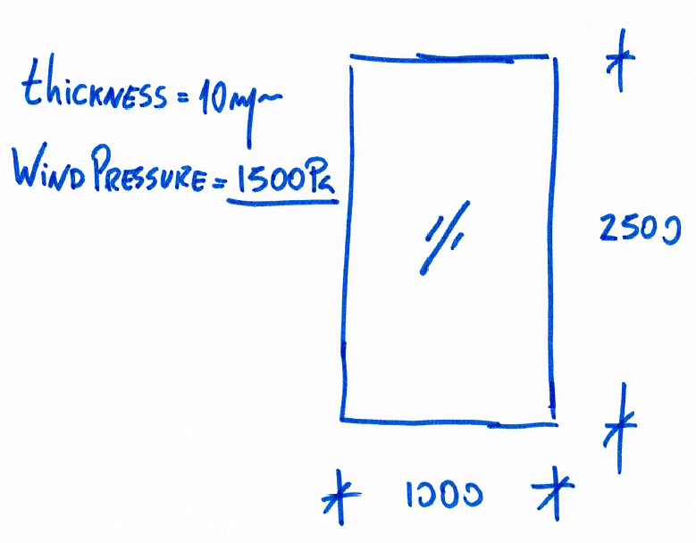
@jjl317 the results from FEA are just to confirm my method. The FEA model consist on a 1000x2500 mm glass sheet with a thickness of 10mm subjected to a wind pressure of 1500 Pa (N/m2).

@rb1957 the software i'm using uses a geometrically non-linear analysis, so i believe there's some kind of membrane forces. But for my excel sheet I prefer to have it doing linear analysis as it is more conservative. Do you have any scheme of your method?


Dear GoncaloPT (Structural)(OP);

The picture , (deformed shape snap ) implies, the the glass is modelled with shell elements and ,more over,(bending +membrane) elements. The supports at the bottom and top also pin support.

That is, membrane forces will develop and the arc length of the deformed shape will not be original ( h() length.

I do not know the software, i think , if you change the supporting con. pin at bottom and roller at the top, ( as shown at 1st sketch9), and run again, you can see the vertical disp. of top support which is deltaH.

Maybe i am somehow out of computer era , (we were the slide rule engineers ) , i would prefer to calculate the deflection amount with the formula suggested by retired13 (Civil/Environmental), and assuming the deflected shape is circle element ( since the deflected shape 4th degr. parabola) find the shortenning as proposed by rb1957 (Aerospace).
 
Based on a quick review, for the information you provided, I find that per ASTM E1300, even tempered glass would be over-stressed, and the deflection perpendicular to glass would be over 2", which would exceed the L/60 that I would typically consider. Not sure which design standard you are trying to follow, but again I think the horizontal deflection and stress are bigger concerns.
 
@jjl317 the FEA results I presented on the pictures above are merely representative. Please don't focus on the 126 mm deflection perpendicular to the glass or stress.
I'm just trying to find a way on how to calculate the vertical displacement of a glass panel when subjected to wind pressure. The glass panel is considered simply supported on the top and bottom (As shown on my first scheme).

So far, with the method @retired13 mentioned for beam deflections I manage to get 17.016 mm, that is a little off the 15.73 mm I got on FEA.
This difference gets worst whit the increase of the Panel Height (L).

Any help is much appreciated.
 
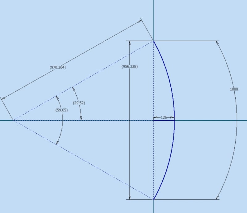
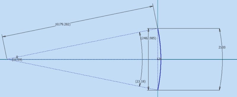
@GoncaloPT Could you please post the span dimension (length) so that we can test the geometric method that @rb1957 suggested? This could also be figured in cad. Here I've used the deflection of 126mm with an assumed span (arc length) of 1000mm arbitrarily.
arc_px0daq.jpg
 
The geometry shown on the FEA results is the following

image_cy1ojs.png
 
@GoncaloPT ok, so using the 2500 mm with the bending deflection of 126 mm and the geometry of the chord of a circle, I get a "shortening" of 17.015 mm.
arc2_xaro78.jpg
 
I doubt the window is producing membrane loads (since there is no in-plane reaction along the edge).

So the window is bending like a plate, mind you a very thing one (10mm thk, 2500mm span) with a significant out-of-plane deflection (126mm = 10x thickness).

The issue is that a membrane has much smaller put-of-plane deflection compared to a plate. Maybe the plate develops membrane action in the middle and reacts the in-plane forces internally ?? I don't think plate vs membrane is a large displacement thing (NL), see what tension (as opposed to bending) the window elements are reacting.

1500 Pa = 1.5kPa = 1.5 kN/m2 = 1.5*220lbf/10.8ft2 = 30.7 lbf/ft2 … ok, a "tiny" pressure. over your window (2.5m2) the load is 3750N = 825 lbf … again, "tiny".

If I doubted the FEA (and I usually do), I'd test the window.


another day in paradise, or is paradise one day closer ?
 
I believe the difference is due to 2D calculation vs 3D modelling. You may get different results using different elements in FEM.
 
@rb1957 - I don't believe that you can find, algebraically, the radius or the angle for the chord, knowing only the arc length and the deflection or "sagitta" (depth of the chord). I could be wrong and hope I'm not missing something obvious, but I'd love to see it worked out.
 
two equations, two unknowns; solve iteratively.

assume a value for R, say 1000 then cos (theta) = 874/1000, theta = 0.5074 but theta is also (L/2)/R = 1250/1000 = 1.25 … not there, try again
(cheat) R = 6178 … theta = acos(6052/6178) = 0.2023 and theta = 1250/6178 = 0.2023

it looks better to say …
theta = (L/2)/R
and cos(theta) = (R-d)/R

so cos((L/2)/R) = (R-d)/R … one variable (R)

another day in paradise, or is paradise one day closer ?
 
I'm having some troubles finding the geomtrical solutions via Excel

The formula I need to solve is the following
image_my6znx.png


I need to find the "R" value for a given "L" and "h". I'm trying to set this with the solver functionality in Excel but i'm not getting it.
Does anyone know how to work this out?
 
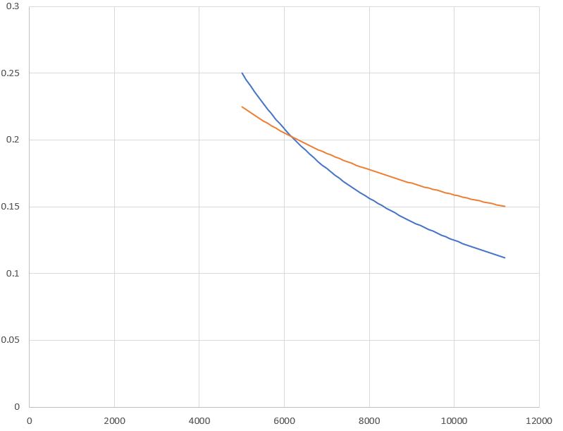
@rb1957 ah I see, the guess and check method. Thank you, that should have been obvious. Another option (essentially doing the same thing) is to plot the two equations over some reasonable range of R values in excel and find the intercept. Both equations will trend towards zero as R increases.
arc3_ls9pgt.jpg
 
excel "goalseek" may help (I haven't used it, but it sounds about right).

graphing is a good way to find trial estimates.

using CAD is fine …

we use which tool suits us most.

the equation "simplifies" to cos((L/2)/R) +d/R = 1 … but still solving algebraically is "taxing".
You could use a series expansion of Cosine ...

another day in paradise, or is paradise one day closer ?
 
I think a plate FEA is over-complicating it, but the differences between different methods are quite interesting, so here goes:

In response to GoncaloPT, the screenshot below shows the use of Goal Seek to solve the equation: L/R - 2 * ACOS(1 - h/R) = 0

Plate_shortening_wmlzho.png


Goal Seek is now under What-if analysis on the Data tab. The "Set cell" needs to be a formula that refers to the "by changing cell", which must be a numerical value, not a formula. I have shown results for a dx of 0.12637 from the original FEA, and 0.12906 from a beam analysis I did myself using Strand7.

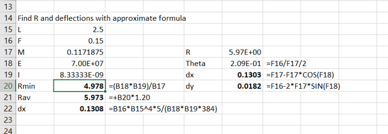
A simpler way, which given the uncertainties in the applied load I think is accurate enough, is to calculate the radius at mid-span (using 1/R = M/EI), then factor that to get an effective average radius over the full length, which allows both the horizontal deflection and the shortening to be calculated quite simply:
Plate_shortening1_asjbjz.png


Based on my own analyses, I found a factor of 1.2 worked well, which gives a dx of 0.1303 and a dy of 0.0182.

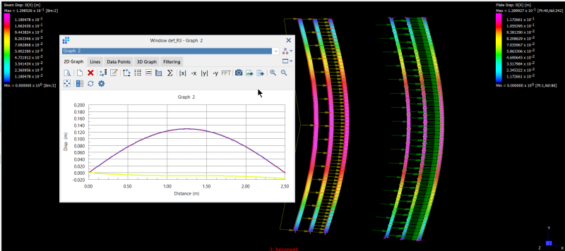
I also looked at using a beam FEA, compared with plates. I also looked at the effect of subdividing the beam into 2, 16, or 64 elements and plates with 16 or 64 4-node elements or 64 8-node elements. The 2-element beam gave almost 20% less vertical deflection, but all the other results were virtually identical, with the analyses with more elements giving marginally more vertical deflection:
Plate_shortening2_iadljw.png


My vertical deflections are about 1mm greater than those in the OP analysis. Possibly a reason for this is restraint of the top and bottom nodes in the Z direction, which stiffens the plate in bending (and doesn't happen in the real structure).

Doug Jenkins
Interactive Design Services
 
Status
Not open for further replies.

Part and Inventory Search

Sponsor