acesareking
Mechanical
- Feb 23, 2020
- 13
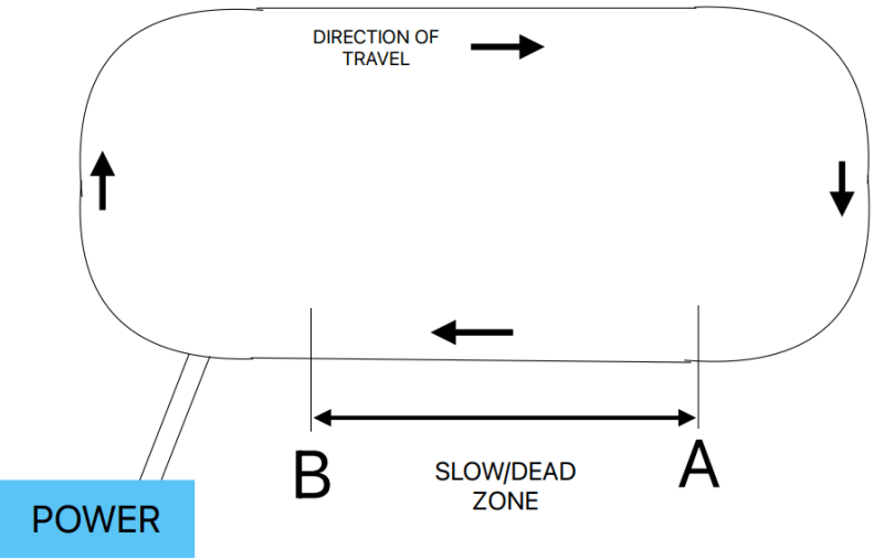
This concerns a model electric car circuit in an oblong shape 8 feet by 13.5 feet. The entire circuit is 43 feet long with 4 equally rounded corners. The drawing is not to scale but is approximately right.
The power is connected to the circuit at the position shown and the cars run smoothly clockwise at a fixed steady speed till they get to the slow/dead zone when they suddenly slow down between there and just before the power supply and then they resume their normal speed till they hit the slow/dead zone again.
I've substituted lengths of track from the fast section into the slow section and it makes no difference to the slowdown in speed in the slow/dead zone.
I can vary the voltage going to the circuit and when I lower it to a certain point the cars will actually stop at the start of the slow/dead zone until I manually pick them off the track and place them anywhere outside the slow/dead zone and then they resume running till they hit the slow/dead zone again.
Can anyone explain why the loss of speed of the cars occurs where it does instead of the opposite point from the power supply?

