Continue to Site

Eng-Tips is the largest engineering community on the Internet

Intelligent Work Forums for Engineering Professionals

  • Congratulations KootK on being selected by the Eng-Tips community for having the most helpful posts in the forums last week. Way to Go!

Circular Plate on CHS/SHS - Yield Line Bending (Effective Length) 2

Status
Not open for further replies.

edomingo

Structural
Oct 3, 2022
5
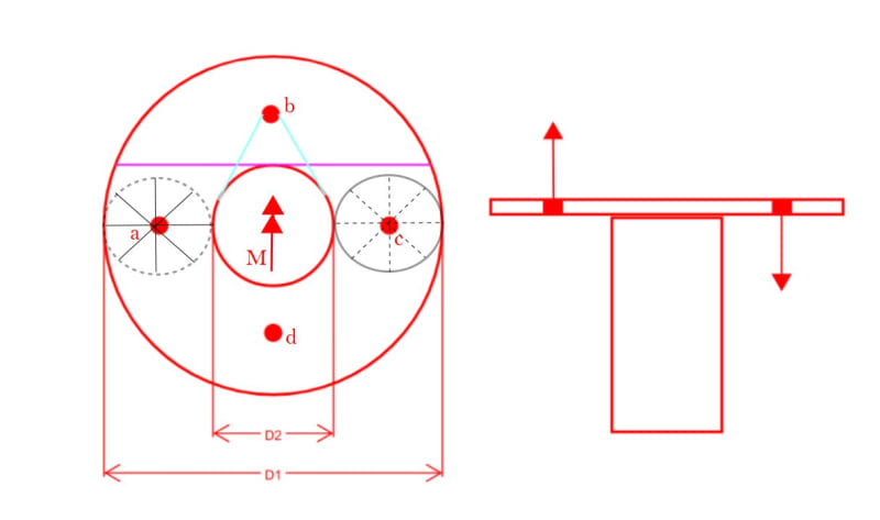
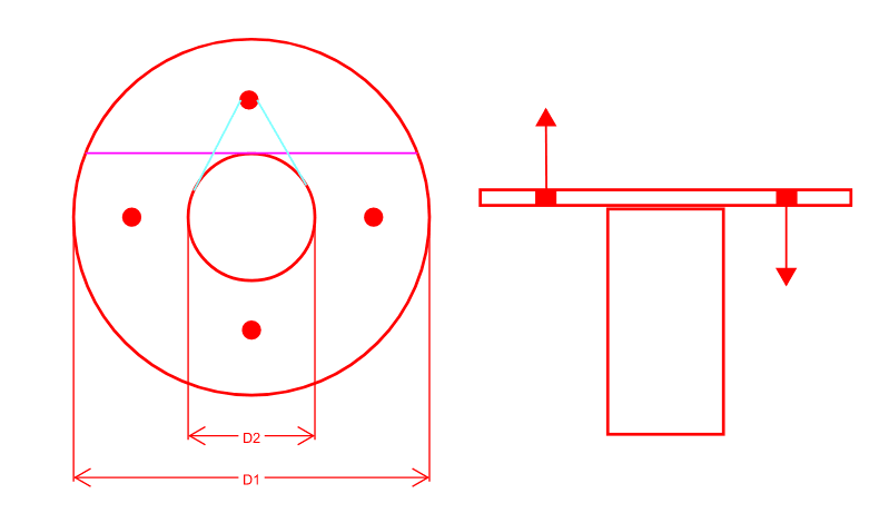
I have a circule plate that supports a piece of a equipment typically on a CHS (sometimes a SHS)and I'm trying to understand my "effective length" that I can assume when checking the plate in bending. I'm not really 100% sure on Yield Line Analysis and I'm trying to have a better understanding on how it works. I have attached an image of what I'm talking about. Is it the purple line? The Cyan Line? Or am I completely wrong?

Screenshot_2023-12-06_162149_eisbze.png
 
Replies continue below

Recommended for you

You are never completely wrong with Yield Line theory. Choose all the legitimate yield lines you can find. When you equate internal and external work, you will find which is critical.

Your purple line is legitimate. The cyan line is not. Can you see why?

The sketch below illustrates one arrangement of bolts and applied moment. If the moment can be in any direction, the purple line and two circular patterns are possible. The purple line is possible when the moment (using the right hand rule) is parallel to a line between bolts 'a' and 'c'. The circular patterns may occur when the moment is parallel to a line joining bolts b and d.

If the direction of applied moment is known beforehand, the bolts should be rotated 45 degrees to the direction of moment. Do you see why?

Using 8 bolts set out at 45 degrees might be a good precaution to take if site errors are to be avoided.

Capture_hzvu4a.jpg
 
Unfortunately, the piece of a equipment has only 4 bolts and is in a circular pattern.

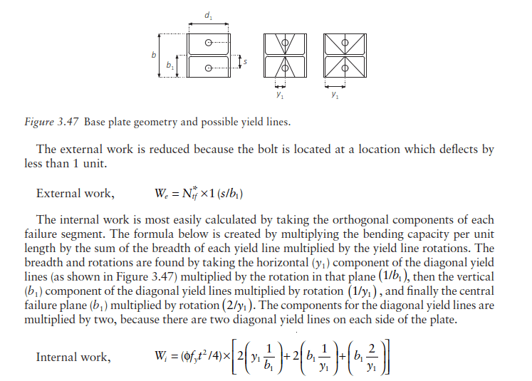
For the effective length of the purple line, it's just simply the length of the purple line correct? However, I'm not understanding how to calculate the effective length to consider for the circular? I understand the concept is taking the horizontal length divided by the rotation but I don't understand the "rotation" part. How would this concept relate to the circular yield line pattern you've noted above? Maybe I'm just stupid and not understanding a basic concept, but I really need help understanding this better.
Screenshot_2023-12-07_133051_sln9fr.png
 
edomingo [COLOR=#EF2929 said:
& BA[/color]]Unfortunately, the piece of a equipment has only 4 bolts and is in a circular pattern.

For the effective length of the purple line, it's just simply the length of the purple line correct? Correct. However, I'm not understanding how to calculate the effective length to consider for the circular? Effective length of the circular yield line is pi*D(diameter). I understand the concept is taking the horizontal length divided by the rotation but I don't understand the "rotation" part. Each small triangle inside the circle rotates an amount theta when the bolt moves up or down. Internal work done = m*theta*pi*D, where m is the unit moment resistance of the plate. How would this concept relate to the circular yield line pattern you've noted above? Maybe I'm just stupid and not understanding a basic concept, but I really need help understanding this better.

Bolts are in a circular pattern, but they are also in a square pattern. If the direction of the applied moment is known, you may be able to find a better orientation for the square arrangement.

For example, would it be more effective to rotate the bolt pattern 45 degrees so that two bolts on each side are contributing rather than just one bolt each side.

 
@edomingo,

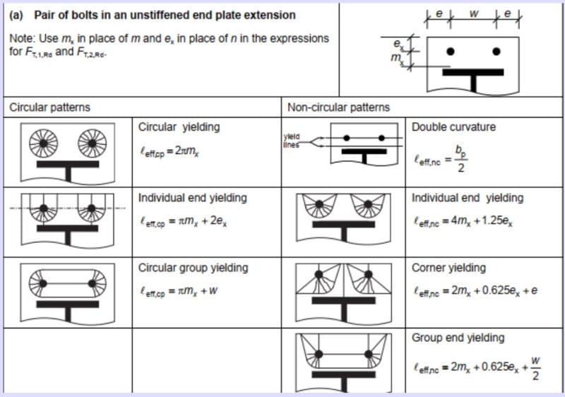
I had not thought about the circular yield lines until a recent post by bkal in thread507-513623 where he talks about the practice in the UK. See below:

Capture_nvxjyu.jpg
 
Status
Not open for further replies.

Part and Inventory Search

Sponsor