Continue to Site

Eng-Tips is the largest engineering community on the Internet

Intelligent Work Forums for Engineering Professionals

  • Congratulations MintJulep on being selected by the Eng-Tips community for having the most helpful posts in the forums last week. Way to Go!

Circulating currents in banks of transformers with star-delta connection 3

Status
Not open for further replies.

diegoz14

Electrical
Sep 18, 2018
6
First of all i want to apologize for the grammatical errors, i'm not a native english speaker, but i really need help with this topic.

I'm an intern in the electrical company of my country, at the present time the company is focusing its efforts to reduce the technical and non technical loses in the distribution system, i was assigned the task of look into the behavior of star-delta connection transformers banks of high consumers, my job is basically use a amperimetric clamp and measure the currents of MediumV (34.5-13.8k)V side, LowV(480-120)V side and circulating currents, also power factor, impedance of the bank and position of the tap's selector. The electrical system in my country has been left behind for decades making it a non-regulated system until now, i often find customers with circulating currents in the LowV side, 8 times higher than the most high line current, note that almost all clients have unbalanced loads and power factor up to 0.9, what makes this to happen? if you see how much current enters in the primary and how much is out trough the secondary you can see heavy losses, what makes the banks to have this kind of behavior? the currents between phases shouldn't be line currents/√3 ? an unbalanced bank in delta will have phase currents higher than the line currents in an effort to "balance" the loads? I know that for a real analysis we need the angles of the currents, but with the information available, what conclusions can we obtain?

HERE YOU CAN SEE A GOOD EXAMPLES OF WHAT I'M TALKING ABOUT

client: ZIPPERs

total kVA: 225

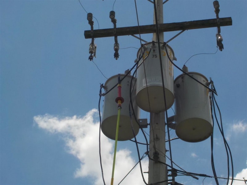
discriminated kVA : 1*75+1*75+1*75 kva

PRIMARY PHASE A CURRENT: 7.5

PRIMARY PHASE B CURRENT: 7.3

PRIMARY PHASE C CURRENT: 7.2

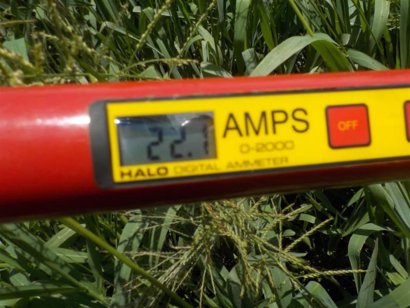
SECONDARY PHASE A CURRENT: 22.1

SECONDARY PHASE B CURRENT: 10.1

SECONDARY PHASE C CURRENT: 15.8

SECONDARY NEUTRAL CURRENT: 34.3

BRIDGE AB CURRENT: 230

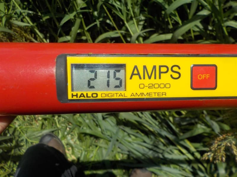
BRIDGE BC CURRENT: 215

BRIDGE CA CURRENT : 225

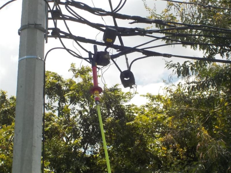
this is the "ZIPPERs" case, here we have a 3*75kva star-delta bank with a transformation relation of 13.8kV to 480/240 v , this bank is used to feed a poultry farm, if you see, the highest secondary phase current is just 22.1 A, meanwhile in the "bridges" that connects the individual transformers into a delta connection, the currents are up to 220 A , i don't know the angles of the currents nor the voltages, this is why i can calculate the real efficiency, if a use only apparent power the efficiency of this case in specific is only 7.22% , and this is not the only case where the efficiency is below than 50%.
DSCN9529_bzrubz.jpg
DSCN9530_mtdy3z.jpg
DSCN9519_naskwk.jpg
DSCN9520_nphv3f.jpg
 
Replies continue below

Recommended for you

Sometimes a floating neutral is suggested as a solution to circulating currents.
A perfect solution in a perfect world.
The floating neutral will eliminate circulating currents caused by line side problems.
Issue #1
It may move the problems to the customers side.
Why are there circulating currents in the first place?
Due to either low voltages or phase angle errors on the primary.
Often both.
Rural voltage regulator banks combined with unbalanced loads are often the cause of down stream circulating currents an a wye:delta bank.
Often unbalanced loading will cause the voltage to neutral/ground to be lower on one phase.
The voltage regulator will correct the lower voltage on the low phase. That will result in unbalances in the line to line voltages and in the phase angles.
The delta diagram will no longer form an equilateral triangle.
But, the back EMF of the customers motors will be equal line to line voltages and equal phase angles.
Now the circulating currents will be in the customers motors rather than in the transformers.
Issue #2
Over voltage switching surges.
Wye:delta banks with floating primary neutral points are known to develop overvoltage switching surges.
Issue #3
Wye:delta banks with floating primary neutral points have issues with single phase switching.
When two phases are energized, the primaries of those two transformers will be in series.
Each transformer will see about one half of line to line voltage. As that is The exact voltage will depend on the loads on the secondaries,
With equal loads each transformer will see one half of 1.73 times normal voltage, or about of 87% of normal voltage.
The secondaries will be displaced by 180 degrees and each of the two secondary phases will develop about 87% of normal voltage.
However the secondary of the third phase transformer will be back fed with only the difference between the other two secondaries and will be at or close to zero.
So, with two phases energized, the customers equipment will see 87% volt on one phase, 87% voltage on the second phase, but at 180 degrees and zero volts on the third phase.
I don't recommend a floating neutral.
Issue #4
Single bushing tanks. Floating the neutral on a wye:delta bank is a serious safety issue. In the event of a single phase loss the touch voltage on the sides of the transformers will rise to dangerous levels.

REALITY CHECK.
You stated load currents of 22.1 Amps, 10.1 Amps and 15.8 Amps.
Load KVA loading of 13.3 KVA

13.3 KVA Load
225 KVA Transformer bank capacity = 3 x 75 = 225 KVA
304 KVA Actual KVA loading due to both load and circulating currents. (7.5A + 7.3A + 7.2A) x 13.8 kV = 303.6 KVA =
130.5 KVA The transformer bank on open delta. 225 KVA x 0.58 = 130.5 KVA

Caution. That circuit is badly unbalanced.
Changing to either a floating neutral or to an open delta will remove the balancing effect of the wye:delta and the unbalanced primary current will show up on the substation metering.
UNLESS there is a second wye:delta bank on that feeder. In that case the other bank/banks will take up the slack and their circulating currents will increase. This may result in blown primary fuse, or, as is often the case when blown fuses are replaced with progressively higher amperage fuse, burned out transformers.
If the voltages at the sub are equal the issue will generally be confined to one feeder.
Unbalanced loads cause unbalanced line voltage drops. This generally isolates the issues to the feeder with the wye:delta bank.

Inoperative individual voltage regulators on rural lines are often a root cause of unbalances.
That is the regulators are working on two phases but the third regulator is inoperative.

By the way: Is the example of the poultry farm on a rural circuit?
Are there voltage regulators either upstream or downstream of the wye:delta bank?


Bill
--------------------
"Why not the best?"
Jimmy Carter
 
Some random notes.
With the primary currents that you show and with the high neutral current, the current in the primary phase with the lowest current is probably reversed, that is the transformer is feeding that much current back into that phase of the feeder.

When changing to an open delta, it is best to balance the feeder so that the neutral current is as low as possible on the primary.
As you work from the wye:delta bank back towards the sub, at each single phase transformer you encounter, connect it to the phase that will result in the least neutral current.
That is much harder to do than to say. The proper balance is a moving target as different customers have differing load profiles during the day.

Open delta has a bad rap for poor regulation.
Yes and no. Sometimes the regulation at a given load is compared to the wrong KVA base and looks worse than it is on a PU basis.
Often an open delta is used to provide three phase power in a rural area where the load is predominently single phase. Excess voltage drop on the neutral conductor can result in poor overall voltage regulation. This may be mitigated to some extent by arranging the single phase loads to reduce the current through the neutral conductor as much as possible.
The selection of an open delta service is almost always the result of a compromise. We can mitigate the problem as much as possible and then live with the compromise.

Changing from wye:delta to open delta when the load appears to be above the reduced capacity of the existing transformers.
Often a large part of the load is single phase.
We may have enough capacity to service the three phase load, but not enough additional capacity to also service the single phase load.
When the transformer bank is converted to open delta, the third transformer may be reconnected in parallel (both primary and secondary) with the transformer which supplies the single phase loads.
Consideration may be given to using a common primary fuse for both transformers in parallel.
With independent fusing there is the possibility that a blown fuse will go un-noticed and that the remaining transformer may be overloaded.

Bill
--------------------
"Why not the best?"
Jimmy Carter
 
I'll take issue with a couple of Waross' issues above.

Issue 1: Floating the primary wye allows the neutral point to shift in order to better balance the primary phase to floating neutral voltage. The secondary voltages are likewise better balanced. Better voltage balance means better current balance in the motors.
With open wye/open delta, the phantom line to line voltage can decrease with some neutral impedance. This voltage unbalance can cause negative sequence currents in the motors. We limit the HP of these systems to 25 because greater loading will cause greater unbalance.

Issue 3: The wye point must be grounded temporally until single phase switching is complete. Some use a permanently mounted disconnect or fuse cutout for this purpose. We use a grounding cable.

Issue 4: You don't need to wait for a fault, the floating neutral to ground voltage will be hazardous during load conditions. You must use dual bushing primary transformers if employing this connection.

 
With respect Steven;
Issue #1:
The primary voltages are unbalanced and/or the primary phase angles are unequal.
This is what is causing the the circulating current.
The circulating current is correcting the primary errors to some extent.
When the neutral is floated the circulating currents stop and the primary unbalances become greater.
Consider a primary circuit with one phase to phase voltage low by 10%.
The nominal secondary voltages are 480 Volts.
One secondary voltage will be 10% low at 432 Volts.
The delta diagram will no longer be an equilateral triangle.
It will be a triangle with sides of 480 Volts, 480 Volts and 432 Volts.
This is still a closed triangle but the sides are no longer equal nor are the voltages equal.
Motors will not like that supply.

Issue #3:
Your following points are well taken and your advice and comments are quite valid.
I agree completely, and an explanation is due.
In the system that we are discussing, the issue is not only with single phase switching of the transformer bank, it is the single phase switching of the entire circuit.
It is common practice on the system under discussion to perform maintenance on dead lines, on Sunday.
Sunday outages are common.
For safety, the work crews disconnect the feeder at the closest point to the work area. These feeders are sectionalized by fused cutouts. At the point of switching the neutral is already grounded and this may be far from the transformer bank.
There may also be the occasional case of a failed fuse on the feeder.

Issue #4 I agree completely. My point was that the voltage is small or zero under conditions of complete balance, voltages, loads, and phase angles. The more unbalance, the greater the voltage.
Whatever the voltage, it may in an instant become lethal without warning.

I appreciate your comments Steven. Others will have the same concerns as you. This gives me a chance to put forward explanations.

Look at the OP's example after doing the math.
Load KVA = 13.3 KVA
Transformer bank capacity = 225 KVA
Actual KVA = 304 KVA
Although this is an extreme case, this is by no means unusual on the system under discussion.
I remember a 150 KVA bank to service a 17 KVA load.
Don't the transformers burn out? Yes they do.
One of my customers lost two transformers. The root cause was a failed voltage regulator on one phase of the feeder.
Things are changing but under the previous management a failed voltage regulator may take a year or so to be repaired.
This is an are where economics and corruption overrule good engineering practice.
The good news is that things are changing and our OP may be able to make effective corrections.
Regarding the voltage regulation of the open delta connection.
I think that you will agree that when the transformer banks are regularly greatly oversized, slightly poorer regulation is the least of our worries.
Thank you for sharing your concerns.
Yours
Bill


Bill
--------------------
"Why not the best?"
Jimmy Carter
 
Issue 1: The issue Waross describes above is a low phase to phase voltage distorting the angles. I agree with the analysis, but find the problem unlikely on a grounded wye system where loads are connected line to neutral. More likely is a low phase to ground voltage caused by excessive loading on that phase with two of the line to line voltages lower. Take three cans of equal impedance and perfectly balanced loading. If the neutral is floated with one phase low, the wye point will assume a position where it is midway between the three phases and voltage magnitudes tend to equalize. I prefer grounded wye/grounded wye services for many of the reasons Waross describes above, but any primary voltage unbalance is transferred right on through. The floating wye/delta connection is able to correct somewhat for these phase to ground voltage unbalances. Angular unbalances are another story, and a severe enough phase to ground voltage problem will distort the angles as well.

I'm unconvinced that oversizing open delta transformers helps with voltage unbalance. The issue is that the neutral carries as much load as the phases. Resistive neutral connections all the way back to the source that normally would go unnoticed will now show up and cause voltage problems with motors. Some systems even have reduced neutrals, increasing the liklihood of problems.
 
Hi Steven.
I have always respected your posts.
Your comments are valid for many systems.
But this is a system that I spent a number of years trying to help customers with power issues.
Rather than counting sheep I have, at times, encouraged sleep by contemplating the issues with wye:delta systems.
I also went to work for a small system which I was able to correct in most cases with a change to wye:wye and in one case with open delta,
A typical problem circuit will be predominantly single phase loads with long circuits and the occasional three phase bank.
As may be deduced by the issues with large circulating currents, there is a lot of unbalance on the circuits.
There are three main causes for this unbalance.
1> The root cause is unbalanced single phase loading. The wye:delta bank, as you know will try to back feed into the lower phase.
2> Rural voltage regulators in normal operation. The common connection is three single phase regulators connected line to neutral.
This does not cause the unbalances but when one phase is low, the phase to neutral voltages are corrected but the phase to phase voltages tend to become more unequal, and the phase angles change a little more for the worse.. The action of the regulator tends to add more current to the neutral and make the issue a little worse.
3> Failed rural voltage regulators. When the regulator on one phase fails to operate, it takes an extremely long time for it to be repaired. Possibly a year or more.

Open delta. I mostly agree with you. I see the regulation issue as one more of the extra voltage drop on the feeder than with the transformer bank. I would not normally oversize an open delta bank for better voltage regulation on a new installation. I am talking about converting to open delta on existing banks that are already grossly oversized.
Were you see the conductor voltage drop extending to the source, in this system, with the predominantly single phase loading, Itis possible to arrange the single phase loads so as to reduce the neutral current and lessen the voltage drop compared to a case where the neutral current is present right back to the source.
In an installation where there is a long feeder to one open delta bank with no or little single phase loading, then I agree with you completely.
And to put it into perspective, with the unbalanced voltages on these systems, a wye:wye system will still cause circulating currents in the motors.

Bill
--------------------
"Why not the best?"
Jimmy Carter
 
Is there any way to rate threads? I give this one five stars! [sunshine][sunshine][sunshine][sunshine][sunshine]
 
Thank you Mbrooke.
And thank you stevenal for your comments.
I don't see that we have any serious differences. What differences that we have stem mostly from our experiences with different system configurations and different operating methods.

Bill
--------------------
"Why not the best?"
Jimmy Carter
 
Status
Not open for further replies.

Part and Inventory Search

Sponsor