I am having a few issues working out the capacity of fixings for a heavy cast iron cladding system to some lightweight steel stud framing. The studs are 150x50x1.2mm lipped channel sections. They are clad in 12mm of gypsum board. Then we fix a stainless steel Z-rail through this to carry the cladding panels - see image
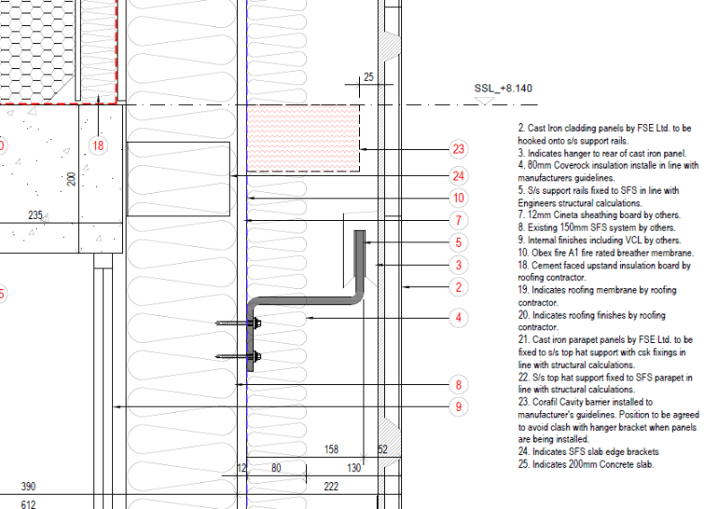
I have assumed the offset creates a moment which is taken by the top screw in tension with the bottom of the Z rail in compression against the plasterboard so then I would need to check the plasterboard for capacity in compression assuming a compression block of some height.
Then I can get published design capacities for self drilling screws in tension and shear but not with an intervening layer of plasterboard. Also even if the screw has the capacity to hold in the 1.2mm stud would I not need to check for local capacity of the sheet metal over the 50mm width between the web and lip of the stud.
The cladding guys assure me this is normal but I am a bit nervous about justifying this. I get a max vertical shear of 640N and a moment of 190Nm at one of these fixing points which gives some big forces with a lever arm of only 75mm between the top screw and bottom of the rail.