Continue to Site

Eng-Tips is the largest engineering community on the Internet

Intelligent Work Forums for Engineering Professionals

  • Congratulations KootK on being selected by the Eng-Tips community for having the most helpful posts in the forums last week. Way to Go!

Clamping analysis

Status
Not open for further replies.

OblongPea

Mechanical
Mar 8, 2023
3
Afternoon,

I don't have a great deal of experience in mechanisms and clamping so was after some help/ advice.

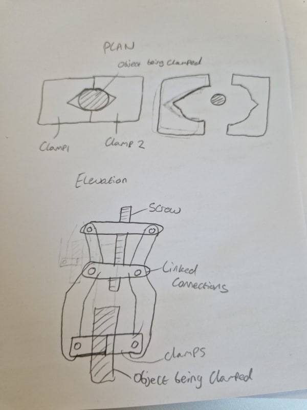
Could anyone help me with this problem attached. I am struggling to understand how to analyse the clamping force required.
The bar to be clamped is 7kg and 10mm in diameter and it must be lifted whilst clamped (cresting 69N force acting downwards)
I have made a concept and need to determine the clamping forces required but
It follows the same clamping mechanism as this:
I assume the reactive force from linkage bar it's attached to can be determined through force vectors.

Any advice on how to analyse this would be very helpful

Many thanks


Replies continue below

Recommended for you

You would start with coefficients of friction, since zero friction would allow the object to slip. Then you would determine whether the pressure would result in deformation of the object or the clamp.

TTFN (ta ta for now)
I can do absolutely anything. I'm an expert! faq731-376 forum1529 Entire Forum list
 
looking at your sketch, I'd have a clearance between the jaws when they contact the "thing to be clamped".

I think you need something like hard rubber on the jaws, something that'll deform under load and not damage "the thing to be clamped".
Then the clearance between the jaws defines the amount of pressure that can be applied (until the jaws "bottom out".

"Hoffen wir mal, dass alles gut geht !"
General Paulus, Nov 1942, outside Stalingrad after the launch of Operation Uranus.
 
Your sketch, shown below, seems to completely leave out the highest pressure sections, which are two vee-shaped notches that are inline with the clamping force. [edit] sorry forgot the picture

20230308_152940_kspw2f.jpg


TTFN (ta ta for now)
I can do absolutely anything. I'm an expert! faq731-376 forum1529 Entire Forum list
 
As others have alluded to, I'd be wary of designing the jaws so that they can bottom out while gripping anything you intend to lift, even when accounting for jaw wear (if that's relevant). That would lead to lower than expected clamping forces, and could lead to dropping the load. Also, you should verify if this clamping mechanism qualifies as a lifting device or not (sounds like it might), based on whatever your local code for that kind of thing is. In the USA (what I'm familiar with), it's ASME B30.20 "Below-the-Hook Lifting Devices" and ASME BTH-1 "Design of Below-the-Hook Lifting Devices". BTH-1 briefly touches on the required clamping force in section 4-9. Note that whatever your local code is likely covers many other aspects of this device, assuming it qualifies as a lifting device.
 
I teach a robotics course and this looks similar to a robot gripper analysis problem.
Equations come from many sources and take many forms, but the one I use is this:

Fg = (WZS) / (μN)

Fg = force per gripper finger applied to load to move the load
W = WEIGHT of payload (not mass)
Z = adjustment factor: Z = 1 (motion of load down with gravity), Z = 2 (sideways horizontal motion), Z = 3 (motion of load up against gravity)....I usually just use Z=3 because I'm always lifting
S = factor of safety (minimum 2)
μ = coefficient of friction (can look this up)
N = number of gripper fingernails (usually 2, 3, or 4)

The comments offered are correct: don't design your fingernails so that they bottom-out on the closure stroke.


TygerDawg
Blue Technik LLC
Manufacturing Engineering Consulting
 
I take it that the upper "link" is 2 1/2s, both angled upwards, and there's a nut on the screw. so turning the screw, flattens the links, and so widens the upper lugs, causing the grippers to close together.

"Hoffen wir mal, dass alles gut geht !"
General Paulus, Nov 1942, outside Stalingrad after the launch of Operation Uranus.
 
@rb1957 that's correct yes. I assume the screw wouldn't be under any load (other than pulling the weight of the payload and links) as the mid connection is a two force link (so forces cancel out, as are the top half links) and the only force would be shearing the connection pins.

@tygerdawg thanks for the equation, I've searched a few repositories but I'm struggling to find a source, as you said they vary massively. Do you have a source for this?

Thanks

 
Oblong:
I don't recall my source. Some old textbook left over from the previous course instructor. I imagine that similar formulas could be obtained from gripper manufacturer's catalogs or engineering guides.


TygerDawg
Blue Technik LLC
Manufacturing Engineering Consulting
 
"I assume the screw wouldn't be under any load (other than pulling the weight of the payload and links)" ...
I don't "think" that's right ... which is why I expanded the description on the links. I think the nut, in travelling down the screw, changes the angle of the links, and the out-thrust (that causes the gripping force) is a component of the load from the nut.

"Hoffen wir mal, dass alles gut geht !"
General Paulus, Nov 1942, outside Stalingrad after the launch of Operation Uranus.
 
Status
Not open for further replies.

Part and Inventory Search

Sponsor