EthanT24
Mechanical
- Jun 14, 2023
- 2
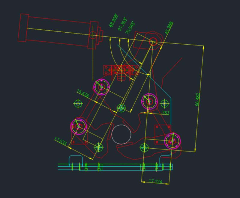
I am trying to calculate the applied clamping torque for each of 3 jaws that are used to clamp the end of a solid steel bar on a bar peeling machine.
Here is what I know:
1. Cylinder pressure = 1,850 psi
2. Cylinder bore = 14"
3. Clamp #1 has no linkage and the moment arm from point of force to rotation point is 46". Force is at an angle of 70.5 degrees.
4. Clamp #2 has 2 linkage joints. I took the orthogonal combined moment and came up with 84.5". Force at an angle of 91.4 degrees.
5. Clamp #3 has 2 linkage joints. Combined moment is 106.5". Force angle is 68.9 degrees.
My calculation using Torque = Force (Cylinder force) * Moment Arm Length (FT) * sin(Force Angle):
Clamp #1 = 1,072,881.17 ft-lbs
Clamp #2 = -580,761.27 ft-lbs
Clamp #3 = -539,324.03 ft-lbs
This seems high. Did I perform this calculation correctly? If not, suggestions are welcome. I have attached a picture of the carriage and dimensions.