Eng-Tips is the largest engineering community on the Internet

Intelligent Work Forums for Engineering Professionals

Clarification of some simple failure scenarios 1

Status
Not open for further replies.

SodaEng

Chemical
Mar 19, 2023
3
0
0
US
Hi all,

I took ASME Sec VIII PSV sizing courses ~5 years ago and remain familiar with API 520, 521, etc. but do not regularly perform PSV sizing exercises. I am hoping someone can clarify how to handle some simple failure scenarios. As I understand it, only one device failure must be accounted for per scenario unless multiple devices would fail due to the same event. In addition, it is my recollection that instrumentation/controls cannot be counted on to prevent a failure scenario.

Scenario 1 - Liquid
A centrifugal pump is controlled by a VFD to maintain a set discharge pressure. The liquid passes through a level control valve into a buffer tank. The only liquid overpressure scenario for this tank is that the LCV fails open. My questions for this scenario:
1. Does this scenario truly count as a failure, since the LCV is open under normal operation and is held in a partially open state by an I/P converter?
2. With the pump being on a VFD, do I have to consider flow conditions on the curve, or am I allowed to use normal operating conditions?

Scenarios 2/3 - Gas
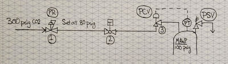
Gas used to pressure the head space of the tank is regulated down to a pressure below the MAWP of the tank. When pressurization is required, the gas passes through a pressure control valve prior to entering the tank. The failure opportunities here are the regulator and the PCV.
1. Similar to the liquid scenario, does the PCV "failing" open truly count as a failure? I.e. if I'm examining a regulator failure, do I have to use the maximum C[sub]v[/sub] value of the PCV?
 
Replies continue below

Recommended for you

I cant follow scenario 1) - and for scenario 2) i dont see a FCV in your description? If the PCV fails open then the gas from a source with a higher pressure than the MAWP of the vessel will continue to enter the tank. Assuming it has nowhere else to go? then i would say size for the PCV Cv, max upstream pressure and SP downstream pressure.

With regards to IPL, since the PSV is the last layer it does not make sense to include the IPL - except for passives such as design pressure (if your MAWP was above the max gas source pressure).


--- Best regards, Morten Andersen
 
1 - LCV fails open. With no/less restriction in line, back-pressure should decrease, VFD should increase pump speed. Quick/conservative way is to size PSV for pump's end-of-curve flow rate, but you can calculate expected flow rate using system curve, and taking into consideration the expected back-pressure from open PSV.
2 - It counts as one independent failure. Depending whose rules you are following, API or your companies, you may or may not have a credible scenario. In my company it would depend if there was enough instrumentation to alarm the operators/staff of a high pressure down stream of the PCV (PCV fails). If not, one could have an “unannounced” failure which provides insufficient recognition that a failure has occurred, and can exist such that a 2nd independent failure occurs before the 1st one is corrected. This is because the FCV may work good enough with a failed PCV that no one notices for some time. But, that is my company's rule. You need to go by the rules your company sets.

Good Luck,
Latexman

 
Your description could do with a bit more information and a drawing.

From the two scenarios my answer is based on the fact that this is a tank (not a PV), but a sealed on which has its vapour space pressure kept at some low pressure (less than 15psi) and / or the MAWP is <15 psi.

IMHO, both scenarios can be considered failures.

If the LCV fails open either due to a fault with the actuator or the I/P controller then I would imagine that the VFD would ramp up to maximum as the output pressure falls.

So your max flow is the max speed of the pump at the lowest possible pressure when the valve is fully open. So max open CV of the LCV and other static losses and frictional losses come into play to determine max liquid inflow.

Same for item 2 - this is a common failure scenario - and yes, you need to use max CV of the wide open inlet valve.

Remember - More details = better answers
Also: If you get a response it's polite to respond to it.
 
All, Thank you for the responses. I see that I had a few poorly worded sections in my initial post. What I was trying to determine, since my understanding is that controls can't be counted on to prevent a failure, is this:

Under a failure scenario of one device, can another device that's being actively controlled - the pump on a VFD for my liquid scenario or PCV on an I/P for the gas scenario - be counted on to run at normal operating conditions, or must the worst case for the controlled device be considered?

Can I assume that the VFD of the pump continues controlling to the set pressure in case of the buffer tank LCV failing? Or must I use points on the pump curve that are at a higher pressure than the set point?

In the case of my gas regulator failing, can I assume that the tank PCV continues controlling to the tank set pressure, or must I assume that it is fully open?

From LittleInch, it sounds like it is appropriate to assume the PCV to be fully open during the regulator failure scenario. This was my intuition, but in this case it leads to a very large PSV size, which I was hoping to avoid.
 
SodaEng said:
Under a failure scenario of one device, can another device that's being actively controlled be counted on to run at normal operating conditions, or must the worst case for the controlled device be considered?

If possible, I rationalize what the controlled device would do, like open or close, and that may not be "to run at normal operating conditions".

Good Luck,
Latexman

 
Normally you find the worst case failure mode.

So in 1, for me, it's LCV fails fully open and then the VFD works as it is supposed to and goes max flow in order to maintain its set discharge pressure which has fallen as the flow increases. i think increased flow is more imporatant than increased pressure, but I don't know your system.

This is where a drawing would help for no 2.

I now see what you mean. You need to look at single failure. So is the worst a regulator going full open and more flow going through the secondary Pressure control valve? or more likely the worst case is the PCV fails in whatever cause and goes full open and the regulator also goes full open trying to provide pressure which has fallen as the PCV has increased flow? However the pressure you calculate the max flow through your PCV could easily be the normal set pressure of the regulator assuming the regulator max flow is > max flow of the PCV.

So chose the max capacity of your regulator carefully. The max capacity of any gas blanket type system is related to max inflow due to liquid level falling or vapour contents suddenly cooling, e.g. in a cold rain shower. V small negative pressures and your tank collapses.

Guarding against higher pressure is often a bit easier.

Does that make sense?

Remember - More details = better answers
Also: If you get a response it's polite to respond to it.
 
Pls note by API, process controls do not count as safety devices at all, no matter how many control loops (self op regulators included) you have installed.
Process safety trip loops DO count, and you can assume no more than one fully independent trip loop has failed.

For the case of gas blowby into a downstream lower operating pressure vessel, there are 2 safety devices, but each of these is not tied into fully independent trip loops : in most cases, these 2 trip devices, the low level trip TX on the upstream vessel, and the high pressure trip TX on the lower pressure vessel act on a common shutdown valve. So if this SDV fails, you've got a credible gas blowby into the downstream vessel.

There are many other considerations to take into account, speak to a process safety engineer if interested. One common corruption of process safety trip loops to watch out for is when Operations use a process safety trip loop as an process operating control loop. In such cases, you cannot take credit for the safety trip loop.

By DIN standards, process control loops are given some credit in reducing the relief load, or maybe even completely eliminating the risk altogether. I am not familiar with controls configuration for these purposes by DIN standards.

Pls note these basic rules dont apply to B31.8 pipeline gas pressure reduction stations / B31.4 liquid pipeline pressure protection systems.
 
Thank you all for your responses. To LittleInch's point, I should have done this earlier, but a simple diagram of my gas feed to the tank is below.

Device (1) is a direct-acting, manually tuned pressure regulator which is set below the MAWP of the tank. This device is sized to allow pressurization of the tank in a specific time period.
Device (2) is an on/off, normally-closed ball valve that opens when pressurization of the tank is required.
Device (3) is a rising-stem control valve that modulates via an I/P converter to control the pressurization rate of the tank.

As I currently see it, devices (2) and (3) failing are irrelevant due to the regulated pressure downstream of device (1) being lower than the MAWP of the tank.
In the case of device (1) failing, I am still unsure whether device (3) must be considered to be in the fully open position. That seems to me to be a multiple-failure scenario. The controllers that would open the path of the high pressure gas to the tank would then have to fail immediately and completely in order for device (3) to be fully opened. I am still unsure how the idea of not accounting for controls as safety devices integrates into this scenario, and what conditions must be assumed.

20230321_092504_2_ytcmp4.jpg
 
A drawing really helps!

A couple of things.

Nomenclature - For me this isn't a tank, it's a Pressure vessel if you're above 15psi and hence other factors, laws and codes of practice start to apply.

Probably not helpful, but can't really see why you can't just get rid of 1 and make 3 a device able to regulate down from 300 psig. Then your failure mode is simply max opening , but then limit the CV or limit the opening mechanically. The you could turn item 2 into some sort of safety trip valve (FC?)

Some of this depend son what the failure mode is of item 3, but with two regulators / control valves in series it does get a bit complex. But if 3 is able to withstand 300 psi without breaking or being over pressured, what is 1 doing for you? If 3 can't handle the overpressure then it shouldn't be there...

Remember - More details = better answers
Also: If you get a response it's polite to respond to it.
 
Status
Not open for further replies.
Back
Top