Eng-Tips is the largest engineering community on the Internet

Intelligent Work Forums for Engineering Professionals

Clarification on my thought process about FE load path needed.

Status
Not open for further replies.

Burner2k

Aerospace
Jun 13, 2015
193
0
0
IN
Hello,
I need some clarification on my thought process.

Lets say I have a cantilever beam with a top plate, bottom plate, web, left & right web support plates. Although not shown in the image, assume they are connected by button head rivets. The beam is subjected to an upward transverse load.

01_nfjzoa.png


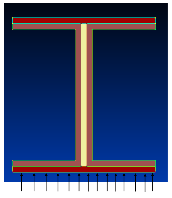
I have represented the same in FE using quad elements and the riveted connections are represented using CBUSH elements.

02_xjayn3.png


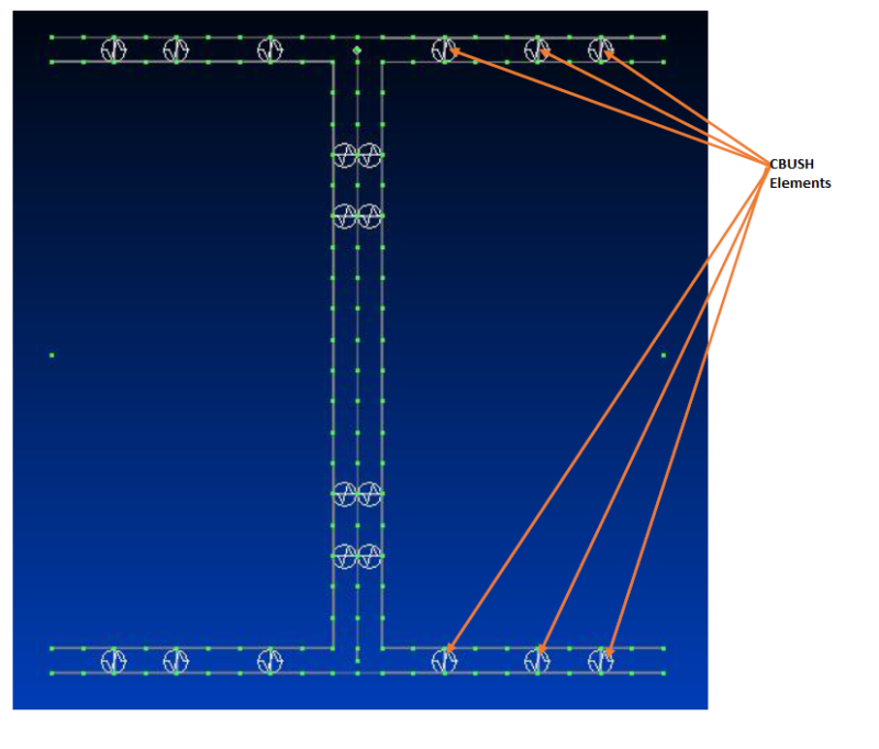
I have not defined axial stiffness for any of the CBUSH elements. The question I have is that, for the CBUSH elements that connect top/bottom plates to web support plates (some of them have been pointed out in the above image, should I define an axial stiffness?

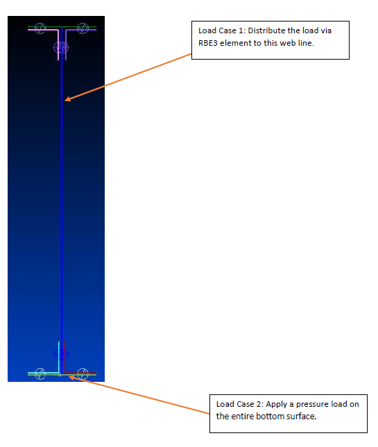
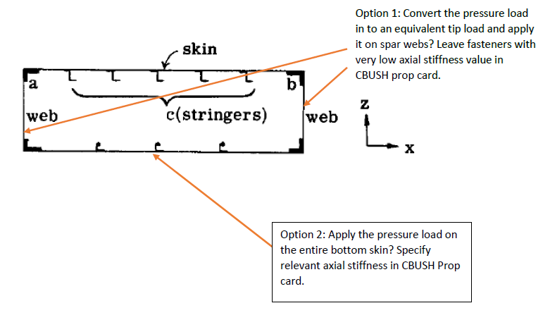
Unless I have defined contact between the surfaces (which I have not), how will the load get transferred from bottom plate to the entire cross-section of the beam?

I actually ran a static analysis and guess what, the bottom plate just deflected upwards going through the web support plates & web. That is, the entire cross section was not effective. This lead to the thought that I need to define Axial Stiffness for them elements.

Would experienced folks here agree with my thought process?
 
Replies continue below

Recommended for you

The level of detail implies you are interested in details of the beam's behavior which will only be revealed by nonlinear analysis. If so, then yes, you need axial fastener stiffness. If you're linear-static, then no, but you also don't need such a complicated model. What are you trying to reveal with your model?
 
as above, why such a complicated model ?

if you want to check the joining pieces, flexural shear calc will tell you what shear is passing form one piece to the next.

with your model the only thing passing load from one piece to the other is the CBUSHs. yes. if the lower CBUSHs don't have axial stiffness and if you don't define a contact area, then where is the lower plate going to ship load ? Contact is the better approach ... making your complicated model only a bit more complicated.

another day in paradise, or is paradise one day closer ?
 
Thanks RPStress & RB1957 for your replies.

Well, actually trying to develop methodologies (& also get a better understanding) for more static analysis of more complicated structures...lets say a built-up skin, spar connection or built-up wing structure.

Sorry I did not make the above clear in my original post. I could not share my actual structure and it is quite similar to the beam I've posted above (although the web support plates can be replaced by spar-caps).

I don't want to include contact currently and will try to run by including axial stiffness to start with.
 
I want to thank folks who responded earlier. Was helpful.

I did proceed with the analysis and wanted to report back along with a few more questions.

I tried applying a point tip load (distributed to the entire cross-section via RBE3 elements). I should have anticipated this going by my previous experience, but missed it somehow. There was lot of local distortion in the flanges due to point load and overall deformation of the beam was not satisfactory.

So I modified the application region to web only (structure with greater inertia) and sure enough the beam deflection pattern was along expected lines. However, in this load application form, presence or absence of axial stiffness in CBUSH elements did not make any difference.

Also, I did try applying a pressure load to the entire bottom skin surface of the FE model. Again the deflection (in the original model scale) looked satisfactory although the peak deflection value was almost 1.5 times the value via hand calcs (the entire cross-section was assumed to be monolithic...not sure if they could make a difference between hand calc value & FE determined). As confirmed by the folks here earlier, a high axial stiffness value in CBUSH elements was necessary for the load to get transferred to the entire cross-section.

01_uf81vz.png


So this brings me to my next question.

I have taken a representative image of a Wing Box from Bruhn.

Also I have severely approximated the varying pressure load in to an uniform one that will be acting on the bottom skin during initial stages of analysis.

02_cvvvw0.png


With the above, I was hoping if possible, experienced folks can suggest which methodology would probably yield a more accurate result and also reflects best practices?

Again thx for the help I've received so far.
 
it looks to me as though there are a very limited number of loadpaths between the various elements, at the CBUSHs assuming no contact. Does this matter ? is there suction on the upper surface that would require rivet tension, or pressure on the lower surface which would transfer by face bearing ? Unless you're after some very specific results, I think your model is over-detailed; if you are modelling a beam, a "caps and web" approach would be reasonable, then hand calc to divide the load between the different members and to calc the rivet forces.

Best practice for loading a wing would be to apply varying pressure (as per CFD) to both surfaces, and of course inertia loads. If in the early days of developing your model, you could apply uniform pressure to both surfaces; but this won't yield accurate results.

Wing modelling ... include the neutral axis off-set of the stringers ... in a narrow wing structure it has an important effect.

another day in paradise, or is paradise one day closer ?
 
There is a good reference written by Ian Taig. I think this is the same reference (have not read through the entire file). Hope this helps.

Like RB says, you need to apply a pressure load to top and bottom of the wing to get closer to "real world". Lower resolution point loads are not what is really happening to the structure (other than jacking, ground loads, etc).
 
You don't say what FEA solver you're using, but since you mentioned using CBUSH elements I can assume you may be using MSC Nastran. If so, MSC Nastran SOL-101 (linear statics) does have the ability to model contact between meshed parts in your model. You simply specify a set of elements as a "contact body" for each part. SOL-101 will automatically assume all defined contact bodies can contact each other. The only requirement, is that the contacting bodies are initially in contact. If they are not, then you'll need to run the non-linear solution SOL-400. So, if you want to use the FEA solver to simulate contact between your parts, this is probably the easiest approach. If you Google "Nastran linear static contact body example" I'm sure you'll fine some good online examples to follow.

Good luck!
 
Hey Cohoman,
Just saw your posting.

I am using NX Nastran not MSC although the syntax is almost similar.

>> The only requirement, is that the contacting bodies are initially in contact. If they are not, then you'll need to run the non-linear solution SOL-400.

Wow. I was not aware of the above for SOL 101. Gotta go back to official docs and look it up. Is it mentioned there?

One of the objective is to develop methodologies on simple models which can be scaled up for more complex models like a Wing etc. Currently, we are not very keen on using contact formulation as it would be expensive to incorporate on complex models but we will have to if they are necessary to get pretty accurate values.

I am having issues even with my basic beam+plates arrangement (some of it I had overlooked earlier). Will make another detailed post tomorrow if I am not able to resolve it by then.
 
I don't know your application, but I'd never model a wing spar this way. I'd use a single 1D element for the caps and 2D for the webs; one element in the web (down the depth) may be a little crude, three are probably sufficient to capture the bending field.

another day in paradise, or is paradise one day closer ?
 
Hi RB1957,
I understand where you are coming from. We are just investigating if going for a more accurate geometry representation would yield us better & more accurate results.

Any good open source reference on calculating deflection due to shear in beams?
 
>> Wow. I was not aware of the above for SOL 101. Gotta go back to official docs and look it up. Is it mentioned there?

Sorry, my comments reflect MSC Nastran. I'm not sure if this initial contact feature is available in NX Nastran.
 
Status
Not open for further replies.
Back
Top