Continue to Site

Eng-Tips is the largest engineering community on the Internet

Intelligent Work Forums for Engineering Professionals

  • Congratulations cowski on being selected by the Eng-Tips community for having the most helpful posts in the forums last week. Way to Go!

Clocked angular dimensions 2

Status
Not open for further replies.

looslib

Mechanical
Jul 9, 2001
4,205
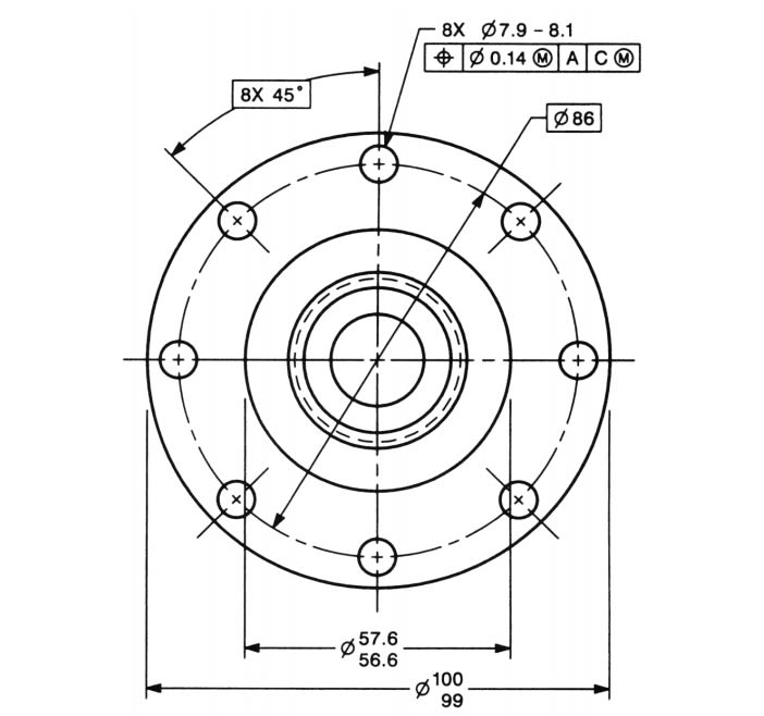
We have a drawing that has a bolt circle with 4 holes on it. The holes are basic angles as is the bolt circle diameter.
The wholes are at the 45 position, so we have 1 dimension of 45 to the first hole off the axis of the part in the drawing.
My questions is, what dimensioning do we use for the other 3 holes with a basic angle: 3X 90 or 4X 90?
I looked in ASME Y14.5-2018, but only shows angular dimensions that are on an axis.


"Wildfires are dangerous, hard to control, and economically catastrophic."

Ben Loosli
 
Replies continue below

Recommended for you

Screenshot_20220304-201454_Office_k8gc1q.jpg


Most people indicate the full number of spaces not because they are told to, but because it makes the most sense. 
If an equally spaced circular pattern runs along the entire pitch circle, how many degrees it occupies? If the answer is 360°, then the sum of the angles indicated by the number of places should equal 360°.  The space between the last and the first hole is part of the basic geometry of the pattern. The purpose of the number of places preceding the dimension is to tell the user how many times the dimension applies to the geometry. So if eight holes equally spaced on a circular pattern has a total of eight angular spaces between the holes, an annotation of eight times 45° reflects it. Look at the figure on the front cover of ASME Y14.5-2009 document, which I posted above. It states 8X 45°, which you don't like because it supposedly contradicts the rule that no more dimensions than necessary to fully define the geometry shall be  given. There are many ways to be sophisticated with the person reading the drawing based on this rule and other Fundamental Rules. If I changed the annotation to 6X 45°, wouldn't that  also be enough for complete definition of the holes' location? There is the vertical centerline crossing both the 12 o'clock and 6 o'clock holes, so according to one of the rules that leads to a definite conclusion that they are at a basic angle of 180° to each other. That leaves only 6 spaces required to define, or isn't it? There is also the horizontal centerline crossing  the 3 o'clock and 9 o'clock holes. So how about 4X 45°? That's all that's needed so that a machinist/inspector worth hiring understands the required geometry, isn't it?  I guess that approach is OK for a designer that only cares about following a very specific set of rules, and not so much about the clarity and interpretability of his drawings. That type of designer is also a good candidate "to be sent looking for some other job". 

 In the linear pattern example you provided, the distance given after the last hole is to the end of the part, not between two holes. With an equally spaced circular pattern, the last hole ends up near the first hole, so there's a slight difference.

You're welcome.
 
Very interesting discussion.
As for how these practices are depicted in the figures of the standard, however, remember
Y14.5 said:
¶1.4.8 Figures
The figures in this Standard are intended only as illustrations to aid the user in understanding the practices described in the text.
(emphasis mine)

"Know the rules well, so you can break them effectively."
-Dalai Lama XIV
 
Hi,

I am surprised that we are still debating on this. As Evan indicated on Feb. 28th, 2022, if the dimensions are basic dimensions for a Position tolerance, then there is no issue.

Hi, 3DDave:

With GD&T, we don't measure dimensions. Rather we measure tolerances in feature control frames. Therefore, your comment below is not accurate.

"I disagree that 8 dimensions for 7 measurements is appropriate."

Best regards,

Alex
 
In the case of 4 holes equally spaced about a center axis can you not just draw centerlines between each of the two sets of holes? This invokes the implied basic 90° angle between all the holes (Y14.5-2009, 2.1.1.3). Add a basic diameter for the bolt circle and you are done.

Sure basic angles might make things clearer, and aren't incorrect, they're just not required.

Thoughts?
 
Status
Not open for further replies.

Part and Inventory Search

Sponsor