Eng-Tips is the largest engineering community on the Internet

Intelligent Work Forums for Engineering Professionals

  • Congratulations waross on being selected by the Tek-Tips community for having the most helpful posts in the forums last week. Way to Go!

Closed loop hydraulic system - Regenerating Electricity 2

Status
Not open for further replies.

hadez202

Mechanical
May 27, 2014
2
0
0
AU
Hi,

I am working as an mechanical engineer in a mining design firm. We have designed a shiploader that lifts and lowers the boom of the shiploader by means of a hydraulic cylinder. What makes this case special is the cylinder is connected to a pantograph meaning the load is not linear during the luffing cycle. I have included a sample of the varying load diagram for your reference below. We are using a closed loop hydraulic circuit with a axial piston variable pump.

Cylinder_and_Loading_Graph_uxvvhl.jpg


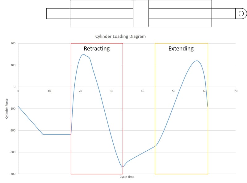
The cylinder that we are using has a has dummy rod on the one side (also in the image attached), therefore we have a pressure ratio of 1:1 across the piston. Seeing that it is a closed loop hydraulic circuit the oil flows directly from the luffing cylinder directly to the pump at the same rate it leaves the hydraulic cylinder (pressure ration 1:1 across the piston). I understand the dynamics of regenerating electrical power making use of a pump which overturns the synchronous motor above the synchronous speed +- slippage and then the motor becomes a generator.

What I struggle to understand with the system, if the pump is delivering oil at a rate of Xm/s to the luffing cylinder on the one side while the cylinder pushes oil out at the other side at the same rate it receives due to the pressure ratio of 1:1 across the piston, the pump will again receive oil at the same rate due to the closed loop system. I therefore assume the oil is recirculating at the same velocity within the system. How can the pump start to turn fast in order to speed up the synchronous motor to generate power? Because the mass flow across the pump is constant.

I would really appreciate some guidance here.

Thanks a lot.
 
Replies continue below

Recommended for you

You mention that pump is variable. The pump is then adjusting displacement to maintain required/desired pressure while the motor runs at constant rpm. Therefore, flow is varying at constant pump/motor speed.
Your force trace shows what appears to be more negative force time than positive force time.

Ted
 
The flow across the pump follows the speed of the cylinder.
It's like having two sprockets connected with a chain and saying one sprocket can't speed up because the speed of the chain is constant.
 
hadez202 said:
How can the pump start to turn fast in order to speed up the synchronous motor to generate power?
The math in this is easier to understand if you make the simulation with a fixed displacement hydraulic motor instead of the 1:1 linear piston. The result will be the same.
If we say that the pump has a 0-100 cc displacement and the motor has a fixed 50 cc displacement.

If you run the pump at a fixed speed of 1200 rpm and want the motor to turn with 600 rpm you need to set your pump at a 25 cc displacement. The speed ratio is 2:1 and the displacement ratio is 1:2
Now you are lowering the boom by gravity and you want the motor (ie the 1:1 piston) to turn with 300 rpm, and you need the pump and the electric motor to turn the same 1200 rpm you will need to adjust (lower) the pump displacement to 12.5 cc. The speed ratio the opposite way, when the motor is acting as a pump and pump, is acting motor, will be 1:4 and displacement ratio 4:1.

To electronically control the pump you will need an rpm transducer on the pump motor shaft and a position (speed) transducer on your linear 1:1 piston. I assume you already are using pressure transducers so that will put your "plc" in full control...
A swash plate position transducer on the pump and temperature sensors will make it even better...
 
How many kW are we talking about?

Assuming you are lifting and lowering something heavy with a closed loop system powered by electricity from the grid but the lifting and lowering is not that frequent (as I think is the case here). Then the economy in the regeneration is not the dollars of electricity generated, the economy is in not having a large cooler or an oversized tank. No extra thinking or parts are needed for regenerating electricity with a closed loop system.
Also no need to regulate the speed, the speed is locked by the grid frequency.

Once again, I don't think there is any money to be made from the electricity itself, it's just the the grid is an excellent way to dissipate energy, simple, large capacity braking power for free.
 
The amount of energy in kW to be regenerated is not what the thread opener, hadez202, is trying to discuss here.
If his application is using X kWh's of energy there is some Y by X kWh's worth of energy to regenerate. This is nothing new. Logging machine manufacturer LogTech I regenerating kinetic back to electric energy while intermittently starting and stopping a tree in the delimbing process. The same thing is done by the excavator industry where the slewing is regenerating the kinetic energy. ALL main manufacturers of excavators are using such applications. Danfoss has a special system for this. Hybrid cars we all know about.
Port crane manufacturer Kalmar and dozens of others are doing the same thing.
In a ship loader where millions of tons are handled this "X" factor is a much larger number than any individual hybrid excavator or car.
The only difference in his case is that the pump is driven by electric energy from the grid and hybrid applications are using fossil fuel.
Every time you raise a mass vertically its potential energy increases. Lowering the same mass is wasted energy if a non-regenerative mechanical/hydraulical brake-system/speed-control is used. Port cranes are one of the biggest target-areas today for regenerating energy.
I don't understand why this application should be less worth than other port loading applications??!!
 
A closed loop system powered by an AC motor of the grid (such as the one described by OP) is regenerative in itself.
Threadstarter says he is aware of this.

No special pumpcontrol needed, no special system by Danfoss or anyone else needed, no extra electronics needed, just start operating and you have regeneration.


Excavators are a different story, they don't have a grid to regenerate to and smaller ones don't have closed loop systems.


"How can the pump start to turn fast in order to speed up the synchronous motor to generate power?"

When you lower the load the pump will immediately try to speed up since the pump now acts like a motor and the loaded cylinder is pushing oil into it.
The first fraction of a second there will be no resistance and the electric motor will start to accelerate but at soon as the speed of the electric motor is just a fraction of a percent above the grid frequency it will start generating electric power back to the grid and hence start acting like a brake. Already when the speed of the electric motor has increased to 3% or so above the grid frequency you have 100% braking power (and corresponding regeneration) and the loaded cylinder can no longer accelerate the electric motor. The system finds this equilibrium for speed almost instantly, not noticeable. An electric motor can brake a lot more than it's nominal power so it can always hold the load.


"Because the mass flow across the pump is constant."


The mass flow across the pump is not constant.
The mass flow across the pump is a function of the pumps displacement (volume per rev.) and its speed.
The mass flow across the pump is not controlled by the operator directly, only indirectly by controlling the pumps displacement (volume per revolution).
So the operator chooses a displacement of the pump by moving the joystick and the pump will speed up a few percent until the electric motor has enough braking torque to hold the load.

Another way to look at it is that the torque applied to the electric motor is a function of the load (pressure) and the displacement of the pump.
The pump/electric motor will accelerate to a few percent above grid frequency until the corresponding torque on the electric motor overspeed torque curve is met and this is the speed you get.
 
Thank you very much for all the feedback and discussion.

Like Akkamaan explained this is exactly why we are doing it. Our calculations indicate that approx. 46% of the energy will be regenerated.

Thank you very much for the explanation Jacc and Akkamaan, it makes more sense. I really struggled to understand how the mechanism and mechanics works within the pump/elect motor and the cylinder pressure works. You guys are the best!
 
Status
Not open for further replies.
Back
Top