Hi,
I'm designing a CLT roof - span in main direction is 6,20 m.
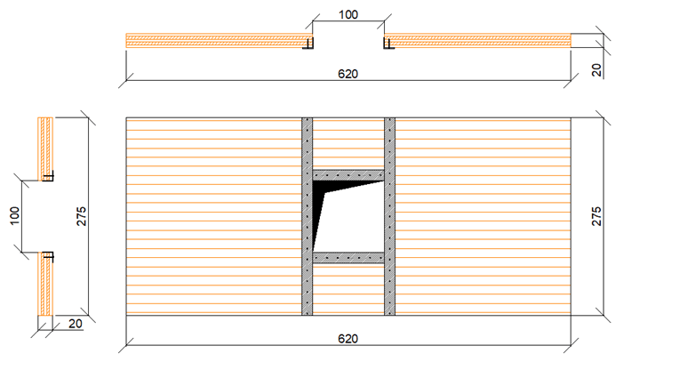
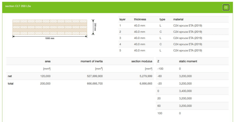
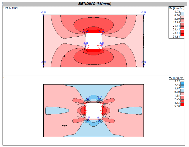
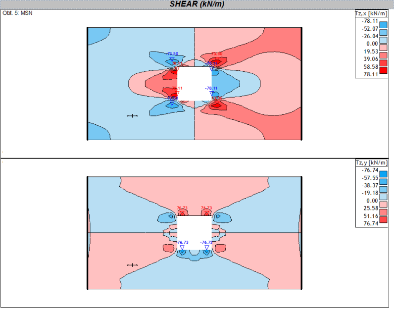
CLT slab is 200 mm thick and it has opening in the middle of the span 1,0 x 1,0 m.
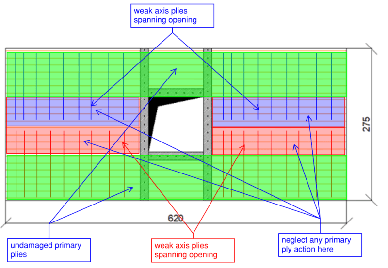
I made FEM analysis and the strip model analysis. I figured that the bending capacity is OK but
I don't know how to approach huge spike of stresses at the edges of the opening?
Would you reinforce them? What do you suggest (steel angles?) and how to calculate it?
Thank you for reply.
Regards.
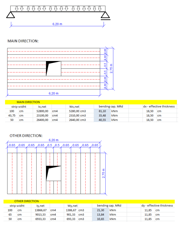
I'm designing a CLT roof - span in main direction is 6,20 m.
CLT slab is 200 mm thick and it has opening in the middle of the span 1,0 x 1,0 m.
I made FEM analysis and the strip model analysis. I figured that the bending capacity is OK but
I don't know how to approach huge spike of stresses at the edges of the opening?
Would you reinforce them? What do you suggest (steel angles?) and how to calculate it?
Thank you for reply.
Regards.