Skogsgurra
Electrical
- Mar 31, 2003
- 11,815
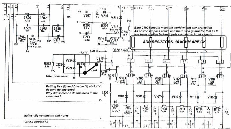
A Siemens Modulpac C board for a thyristor drive behaves erratically. It took some time to find what caused the sporadic malfunction, but it seems to be a 4502B (4xNOR) IC that loads a bias circuit haphazardly.
I have no idea why the designer (Siemens back in the seventies) put a voltage divider from -15 V to 0 V. The divider has a 3,3 kohm and a 330 ohm resistor to produce around 1.4 negative volts for the Disable input (pin 4). Probably to harden the Disable input somewhat to avoid transient blocking of the gating pulses it produces.
I finally found out that the -1.4 V didn't stay put. It is mostly between -0.4 and -1.2 V. Gating pulses are produced when pin 4 is at -1.0 V or lower.
There are several suppliy voltages for the board (+15, +12 and -12 V) and there is no guarantee that the voltages are cycled correctly when the board is inserted in the live system.
There are no resistors or any protection at all between the edge connector and the inputs of this rather sensitive CMOS circuit. I start to think latch-up with some kind of partial destruction of the circuit and that there is a leakage current going to the voltage divider so the nominal 1.4 moves upwards irregularly.
The problem is that I do not have any replacement. And it seems to be a rare bird.
Questions:
Latch-up usually destroys a CMOS gate. These work, but not very well. Anyone had this before?
Where do I find a 4502B? The only place I can find them seems to be in old data books.
The board is quite important and the paper mill doesn't have any spare other than this one. And it is definitely not a spare any more.
Gunnar Englund
--------------------------------------
Half full - Half empty? I don't mind. It's what in it that counts.


