Eng-Tips is the largest engineering community on the Internet

Intelligent Work Forums for Engineering Professionals

VFD blow up 8

Status
Not open for further replies.

james64

Electrical
Oct 16, 2012
46
0
0
CA
Hi all,

I am experiencing a problem with a VFD that seems to be getting damaged when the motor starts. The overcurrent protection of the VFD is set to around 70A, while the motor has a full load current of approximately 80A, 600V, 3-phase at FLA. I am wondering whether the issue may be caused by an inrush current or other reason.
 
Replies continue below

Recommended for you

Thank Waross,LittleInch,jraef and TugboatEng..


Thank you for your tips.If we plan to purchase a VFD, it's important to verify the vendor beforehand. We have already complained about the broken VFD, but they are insisting that we purchase a new one.


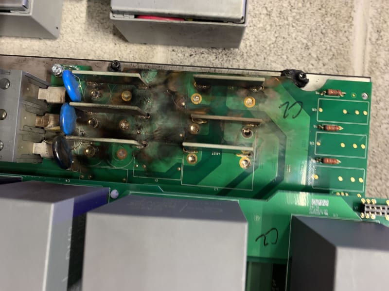
Thank you for sharing the photos. I saw a VFD blow up for the first time, and it was a surprise.
 
To be a bit fair to the vendor, you haven't really investigated or proved what happened and where external events caused the issue.

Unless you can show no impacts then they will probably just blame installation errors or external events.


Remember - More details = better answers
Also: If you get a response it's polite to respond to it.
 
After checking the site, I noticed that the cable length would be around 50ft from the panel to VFD. The cable was inside a rigid conduit that was well-bonded to the ground. There has been an explosion on the AC incoming side of the VFD, causing the incoming circuit breaker to trip as well.
IMG_9819_v2qwia.jpg
. According to the motor specification, the full load amperage (FLA) is around 36.8A. The variable frequency drive (VFD) has 40HP with 63A and a circuit breaker rated at 100A was installed for this motor. "Was everything of the correct value?"
 
Those blue things are metal oxide varistors. They shunt transient over voltages. They have a limited amount of energy they can dissipate. A failure as you have seen indicates an extended over-voltage.
 
Thank TugboatEng for your comment !! I am wondering if the overvoltage issue is a result of not having a line reactor between the AC incoming and VFD input. I am not sure how this overvoltage occurred.
 
I investigated some failures on heat pumps in a rural area. The MOVs had operated and the main control boards had failed in nearly a dozen heat pumps in the area. It turned out to be due a tree in the line - all failures were on the unfaulted phase. Comparing the ITIC/CBEMA curve ratings versus the utility effective grounding requirements (and I also looked up the MOV specs) there is a design gap where electronic equipment can be damaged by utility voltage rise on the unfaulted phases during a ground fault (fault induced overvoltage).
Not saying this is what caused your issue, but just an example of one possibility - utility overvoltage, perhaps due to a fault on the utility system.
 
If the caps have been left unenergized for long periods of time, they can pop on start up. Years ago Allen Bradley used to advise not applying full voltage to a drive that has sat more than a year. They used to recommend that you use one VFD to bring another VFD up to voltage, ramping the voltage slowly. Then let it run an hour. Then connect to the grid.

There are also control settings in the VFD that could help things. Look at your motor speed controls. The most common are open loop vector and V/f. If you are careful about your set up, and using reasonable acceleration and deceleration times, you can keep your inrush to below FLA. If you set the acceleration too fast, the VFD is going to do what it can to meet your requirements, and that might cause a considerable amount of inrush. This will increase the chances of failure.
 
Status
Not open for further replies.
Back
Top