Navigation
Install the app
How to install the app on iOS
Follow along with the video below to see how to install our site as a web app on your home screen.
Note: This feature may not be available in some browsers.
More options
Style variation
-
Congratulations cowski on being selected by the Eng-Tips community for having the most helpful posts in the forums last week. Way to Go!
You are using an out of date browser. It may not display this or other websites correctly.
You should upgrade or use an alternative browser.
You should upgrade or use an alternative browser.
CO2 Liqufaction Flow Issues
- Thread starter co2abc
- Start date
- Status
- Not open for further replies.
horacio Torres
Chemical
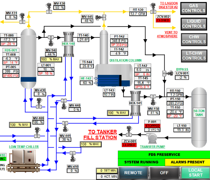
The PFD comes from a simulator or is a screen from a DCS. In both cases, which is the simulator? or is a DSC a Yokokawua ????
Horacio
linkedin.com/in/horacio-torres-molina-429a7b1b
georgeverghese
Chemical
But MV-150 shows 41% open only - if there was difficulty flowing through from reboiler to 50ton tank via chiller HEX 141, then reboiler LCV would be close to 100% open?
- Thread starter
- #4
georgeverghese
Chemical
At 20bar abs / -30degC downstream of the reboiler LCV going to the storage tank, it is subcooled liquid CO2 according to P-h diagram for CO2 ( subcooled by 10degC at 20bar abs), so no problems there. So temp control at rundown chiller HEX is probably working as it should.
Could there be an internal leak between refrigerant side and liquid CO2 side in this HEX? Can you tell us more about this chiller and refrigerant ?
a) Refrigerant description, composition, operating pressure range and temps in chiller HEX
b) Liquid Co2 operating press range, temps in chiller HEX
c) Chiller configuration, TEMA type, design press / temp
Hi,
To support your investigation a handbook about CO2.
As suggested check for abnormalities around equipment using the diagram and tables given to you.
Always start with big picture before going to details.
BTW did you check the process book and data from start up? Mass balance, operating T, P, Flow), valves opening. E.T.C
This is very basic for a process engineer.
Pierre
LittleInch
Petroleum
Can you post the PFD and the P&ID as there are often lots more valves and connections than the schematic shows.
Remember - More details = better answers
Also: If you get a response it's polite to respond to it.
Remember - More details = better answers
Also: If you get a response it's polite to respond to it.
LittleInch
Petroleum
Also FIT 150 is the only flow figure in that schematic. If its not flowing to the tank where is is going? Or it doesn't exist?
Remember - More details = better answers
Also: If you get a response it's polite to respond to it.
Remember - More details = better answers
Also: If you get a response it's polite to respond to it.
- Status
- Not open for further replies.
Similar threads
- Replies
- 20
- Views
- 5K
- Replies
- 24
- Views
- 6K
- Locked
- Question
- Replies
- 9
- Views
- 1K
- Locked
- Question
- Replies
- 5
- Views
- 3K
- Locked
- Question
- Replies
- 4
- Views
- 1K

