Continue to Site

Eng-Tips is the largest engineering community on the Internet

Intelligent Work Forums for Engineering Professionals

  • Congratulations GregLocock on being selected by the Eng-Tips community for having the most helpful posts in the forums last week. Way to Go!

Cocentricity verification

Status
Not open for further replies.

Kalabagh

Mechanical
Mar 16, 2016
8
Hey there,

My question is very simple.

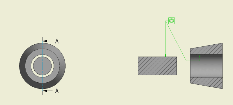
Which would be the phisical procedure to validate/measure the concentricity of a shaft into a hub like the ones of the picture:
Captura_dxecgj.png


As it can be seen, I can't use the external cylindric wall of the hub because it is conical and, let's say, it has a low quality surface finish.

This eccentricity would come from the fact that the hub is part of a subassembly and the shaft comes from another and, once assembled, the circular clearance in between is finally filled by a precise or fragile part that implies certain concentricity between the shaft and the hub to be validated before.

Thanks in advance.
 
Replies continue below

Recommended for you

If I'm understanding your question correctly, you are assembling a shaft into a bore and the bore is being damaged during assembly? You want to verify the parts are concentric before they get assembled? For this, removable dowels or pins are often used to guide to the parts into their final location. What approximately is the scale of these parts?
 
You have not provided nearly enough information to answer your exact question. So, I will turn it into a theoretical question and answer that one.

Question: How can I verify that a shaft passing through a bore within my machine is concentric to that bore?

Answers:

Attach a dial indicator to the shaft, rotate the shaft while reading against the bore. Calculate the concentricity based the indicator reading and the measured bracket sag.

Assemble the shaft within the bore and use feeler gauges or reference pins to measure the gap at multiple locations around the bore.

Infer the concentricity from a series of other measurements. Use a coordinate mapping machine to measure the concentricity of the shaft to its sub-assembly. Measure the concentricity of the bore to its sub-assembly. Measure the fit between the two sub-assemblies or between the two sub-assemblies and the main casing of the machine. Calculate the resulting concentricity allowing for the accuracy of each individual measurement and the stack-up of errors based on the combination of all of these measurements.

Manufacture a dummy shaft that can be installed in place of the actual shaft. Make the diameter of the end of the dummy shaft equal to the maximum size that could still fit within the bore if the concentricity is within your require tolerance. Coat the end of the dummy shaft with contact blue compound and assemble the parts. Disassemble the parts and inspect for any transfer of bluing from the dummy shaft to the bore indicating that they touched.

Machine the outside conical surface of the hub so it is concentric to the bore and has a suitable surface finish to allow for a dial indicator sweep of that surface. Mount a dial indicator in the end of the shaft and sweep the conical surface to measure the run-out. Calculate the concentricity of the shaft to the conical surface based on the dial indicator reading and the measured bracket sag.

I could probably come up with 20 more theoretical solutions. But, without details about your machine and the relative size of these parts and the clearance between them, it is possible that none of my solutions would work for your machine.

Johnny Pellin
 
Hi Mr. Pellin,

You have completely understand my question, that's great.

I like your first answer. But I don't know which type of dials exist. is there a dial able to measure bore concentricity?? Can you post some picture or redirect to somewhere?? It's difficult to find information of that kind of things.

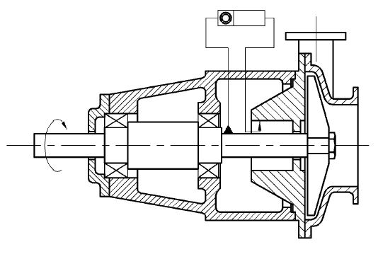
Maybe this picture will be more understandable:
Captura_wodyhl.png


As you can see, the diameter of the shaft and the bore is not the same, but concentricity is needed as the mechanical seal has to be assembled there. The measurement should be done after some minutes running to see that the shaft/bearing/etc have not suffered any problem.
 
What is your concern?
If the pump shaft runs true in relation to the bearing frame female spigot and the pump case male spigot and stuffing box were machined in the one set-up which is the norm, the pump shaft will be concentric with the stuffing box bore.

It is a capital mistake to theorise before one has data. Insensibly one begins to twist facts to suit theories, instead of theories to suit facts. (Sherlock Holmes - A Scandal in Bohemia.)
 
This is normally handled at the design stage by finding the limitations on the candidate seal for runout of the shaft to the seal housing and then allocating that allowable variation to tolerable variation (tolerance) among all the other parts, realizing that some of that allocation will by selecting suitably precise bearings. Since it is an overhung shaft there is a multiplier effect for each bearing's contribution via runout and clearance. That multiplier will be different for each bearing as each has a different amount of leverage.

This allocation allows each part to be inspected for conformance so that one can be confident that the assembly will function correctly.

Radiographic inspection might work for checking if that work wasn't done.
 
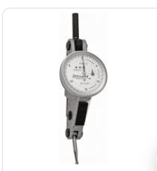
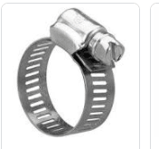
The measurement you are describing is one that we take many times every day. The size of your seal chamber and shaft will dictate what sort of dial indicator will work the best. In order to be able to take this reading on a small pump I would get a last-word dial indicator and attach it to the shaft using a simple hose clamp. I would read the run-out of the seal chamber bore in a full sweep. The concentricity would be calculated by taking the total indicator run-out and dividing it by two.

The pump manufacturers will always claim that their pump is well designed and manufactured to meet their specifications. It often is not. We regularly find this concentricity is poor and we correct it in our shop.

In addition to measuring the concentricity, you should measure the perpendicularity of the seal chamber face to the shaft. You can do that with the same dial indicator reading against the axial face of the seal chamber.
Capture_grrfbo.png


Johnny Pellin
 
Hi Johnny,

If I have understood you well, the way is to put your reference to the shaft by attaching the dial on it so your measurement will be the relative between the shaft and the bore. I expect to have Ø25, Ø35 and Ø45 on my shafts so, is there any clamping accessory directly able for these diameters?? The bore will be Ø47 for Ø25 shaft (radial clearance: 11 mm).

I will perform more measurements, not just this one.

Thanks.
 
I would use a standard hose clamp to attach the indicator to the shaft.
Capture_bvizxn.png


If you are concerned about scratching the shaft, wrap it with masking tape.

There are chain brackets designed for mounting dial indicators to a shaft. Starrett makes some very nice kits for this.

Johnny Pellin
 
Generally I would be more concerned, assuming there is a problem to be concerned about, of bearing clearances both axial and radial, shaft deflection if running off BEP or intermittent loading of the pump.

Do you have a problem, if not why worry about something that isn't a problem.

It is a capital mistake to theorise before one has data. Insensibly one begins to twist facts to suit theories, instead of theories to suit facts. (Sherlock Holmes - A Scandal in Bohemia.)
 
Status
Not open for further replies.

Part and Inventory Search

Sponsor