Continue to Site

Eng-Tips is the largest engineering community on the Internet

Intelligent Work Forums for Engineering Professionals

  • Congratulations KootK on being selected by the Eng-Tips community for having the most helpful posts in the forums last week. Way to Go!

Cohesive Elements in a single part -> How to implement contact?

Status
Not open for further replies.

WillingToLearn

Student
Nov 13, 2021
13
Hello everyone,

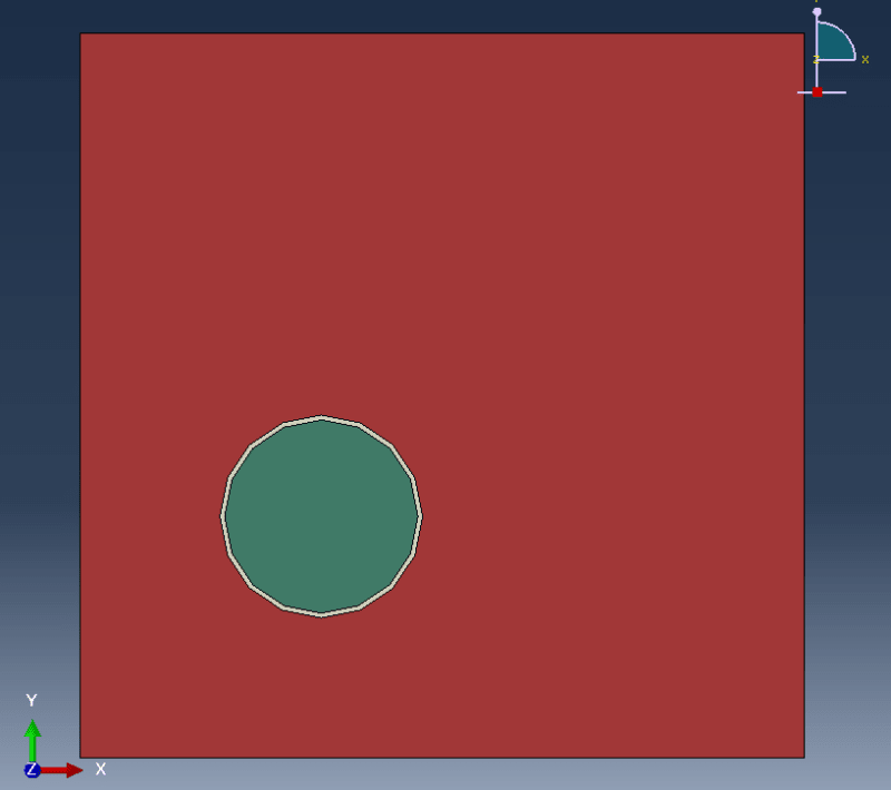
I am trying to model a fiber reinforced part:
FibreExample_j6mket.png


This is a single part with internal boundaries. The white/grey area represent cohesive elements. Now I am wondering how I can deal with compressive failure of the cohesive elements.

Once the cohesive elements fail, there is no more connection between the fiber (green) and the matrix (red). The Abaqus manual suggests contact conditions, but for some reason I can't apply them to this geometry (the green area is not considered a separate surface and therefore can't be selected).

How do I best deal with the compressive failure of the cohesive elements?

Kind regards
Mike
 
Replies continue below

Recommended for you

If you want to define contact, you should model these parts separately instead of using partitions on a single part.
 
I have now a setup that looks like this:
Seperate_parts_h4brhq.png


What is now the best practice to combine the different components?

For the first time step I have to bind the green to the white (cohesive) and the white to the red area -> Should I use tie constraints for this?

And for when the cohesive layer fails I define contact conditions for the green (fibre) and red (matrix) part, right?

Kind regards
Mike
 
How does an adhesive fail under compression? It can yield and plastically flow, but this is not a compressive failure. Adhesives fail where the local stress is actually tension.
 
There are two ways to connect cohesive elements with the rest of the model - shared nodes or tie constraints. Failed elements can be deleted from mesh and then general contact should handle the interaction between the remaining parts.
 
Thank you both for the elaboration.

@Compositepro: You are of course correct and I did not consider this aspect (I found out, that even the Abaqus does not consider compressive stress for damage initiation - I did no know that before and basically wanted to take care of that). However, something strange happened when used a single part with only internal edges (which led me to wrongly believe that the adhesive layer did fail due to compressive stresses):

Abaqus_one_part_xuuu8f.png


So the matrix (red) penetrated the fibre (green). Of course, this should not happen as there is the cohesive layer in between (and the shear stress should not be high enough to cause failure).

When I do the same calculation, but with separate parts (loads/boundary conditions/etc. is all the same) the result looks much more plausible:
Abaqus_multiple_parts_skylml.png


Maybe cohesive elements are not supposed to be used within a part and has to be a separate part?
 
What is the deformation scale factor used for these images ? I would definitely stick to the approach with multiple parts.
 
+5.926e-01 for the second one (as it is still open - I assume it is the same for the first one - if it is important I check it). The geometry is modeled in µm. Will do so - but if anyone has an idea what causes this strange behavior I a
 
Status
Not open for further replies.

Part and Inventory Search

Sponsor