Continue to Site

Eng-Tips is the largest engineering community on the Internet

Intelligent Work Forums for Engineering Professionals

  • Congratulations GregLocock on being selected by the Eng-Tips community for having the most helpful posts in the forums last week. Way to Go!

Cold formed steel truss design

Status
Not open for further replies.

Juhiimi

Structural
Mar 12, 2022
16
Hi all!

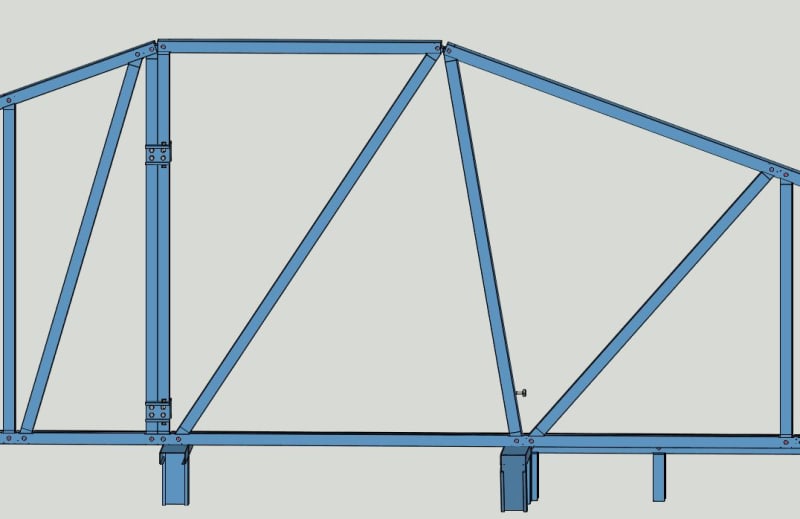
What is the best solution, if I have a CFS truss like the one below where I have the support and the discontinuity in the top chord so close to each other? Do you think it's ok how I designed it?(the doubled vertical members are perforated so the diagonal can go through)
truss_x1wijl.jpg


This is an in plane truss, the firm where I work, does mostly in plane trusses so I can't really go with out of plane.

Thanks!
 
Replies continue below

Recommended for you

I'm assuming the corridor walls are load bearing?
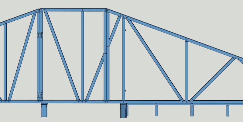
I would take the vertical web over the right wall and make it a diagonal that runs to the pitch break in the top chord. (keep the bottom over the corridor wall) That gets rid of the funky interrupted diagonal. Then maybe just use one diagonal in the panel over the corridor.
Looks like you are using "track" for the top and bottom chords. Hard to get enough screws in that to be effective.
The devil is in the details with CFS framing - especially trusses. I hope you have someone looking over your shoulder - besides us.
 
Something like this? Looks a little odd...
truss_2_xsoojn.jpg


Well I always check the axial forces in the diagonals and check if the screw's can resist the shear force and the bearing resistance of the plate and if I have to I double the member so I get more screws in the joint. Do I have to check something else?

(We have a more experienced engineer in our office who helps us (5 year experience in CFS design) but sometimes I got a feeling that he is too bold, especially when he has to give solutions to my problems...)
 
Looks normal to me, remove the other double member as well following the same logic
 
Also, another reason track is not great for chords is that its weak axis must resist the moment due to the "work point" of the webs potentially being outside the member.
 
With the suggested design above, I have a problem that the top chords are not connected so I guess I have to screw with some plate together.

XR250 yeah that's a problem. How could I introduce the effect of the joint eccentricity in the structural analysis program? Simply by drawing it eccentric?
 
Juhiimi said:
How could I introduce the effect of the joint eccentricity in the structural analysis program? Simply by drawing it eccentric?

That is how I would handle it. Maybe add a little extra separation to account for a lack of precision in construction.
 
Status
Not open for further replies.

Part and Inventory Search

Sponsor