Continue to Site

Eng-Tips is the largest engineering community on the Internet

Intelligent Work Forums for Engineering Professionals

  • Congratulations SSS148 on being selected by the Eng-Tips community for having the most helpful posts in the forums last week. Way to Go!

Cold Joint at Shear Wall to Diaphragm Connection. Check shear friction or not?

Status
Not open for further replies.

chou09

Structural
Oct 23, 2018
3
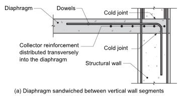
Hi, I am reading the design guide ''Seismic Design of Cast-in-Place Concrete Diaphragm, Chords, and Collectors''. In the guide it says ''Where the diaphragm is sandwiched between vertical wall segments, shear friction requirements must be satisfied through monolithic concrete at face of the wall using dowels and through the two cold joints using a combination of wall reinforcement and dowels''. Please see attached detail below.

According to our engineers, they never consider those cold joints as shear friction in new construction. The roughen face will interlock the concrete, so the wall can be treated as one piece.

My questions are:
1. Do we need to check the shear friction at those two cold joints?
2. If so, should we use only vertical rebars in shear wall for the check? Or can we account for concrete strength also?
3. Do we need to apply omega factor for the check?
 
 https://files.engineering.com/getfile.aspx?folder=e5e5bf9a-55fe-4ee5-b1df-6455f992a77e&file=Capture.JPG
Replies continue below

Recommended for you

Here's my take:

1. Do we need to check the shear friction at those two cold joints?
[blue] Yes...even if monolithic you have shear forces across that "line" and need to verify that it can take it.
If a cold joint - the shear friction with the appropriate surface factor. If monolithic, by observation you can "check" the shear as OK there presuming the wall itself can successfully resist the shear as a shear wall...so it might become "OK by observation".[/blue]

2. If so, should we use only vertical rebars in shear wall for the check? Or can we account for concrete strength also?
[blue]Shear friction checks use the rebar as one derivation and then have a ceiling on the value using the concrete area (per ACI 318).[/blue]

3. Do we need to apply omega factor for the check?
[blue]For wall-to-diaphragm transfer I don't think that it is required. Omega is required for collectors in diaphragms. Design would be per ASCE 7-10, section 12.11.2 [/blue]

Check out Eng-Tips Forum's Policies here:
faq731-376
 
OP said:
they never consider those cold joints as shear friction in new construction.

I don't think that you have the option to not consider cold joints as shear friction joints if you're in an ACI jurisdiction. Shear friction is really the only tool they give you for this.

OP said:
The roughen face will interlock the concrete, so the wall can be treated as one piece.

I disagree with this. Roughening gets your a shear friction joint with better mu values. It does not allow you to treat the joint as monolithic and thus ignore the shear friction calculation.

OP said:
Do we need to check the shear friction at those two cold joints?

Yes

OP said:
If so, should we use only vertical rebars in shear wall for the check? Or can we account for concrete strength also?

As JAE alluded, the shear friction method utilizes the properties of the steel and concrete working together. There's no "extra" to be gained by double dipping and adding a separate concrete contribution. The concrete "zipper" that provides the shear resistance is really a strut and tie system in micro with the concrete as the struts and the steel as the ties (obviously).

OP said:
Do we need to apply omega factor for the check?

In my opinion, it is appropriate to apply omega. This is a critical, low redundancy connection between the LFRS and an element aggregating diaphragm shear. This strikes me as being philosophically identical to a collector to LFRS connection.
 
KootK - I looked for a reference, any reference, to the use of Omega for diaphragm to wall connections but didn’t see any in ASCE 7 or ACI 318. Not sure what Canada codes say.

Do you have any direct code that you know of that requires it?

Check out Eng-Tips Forum's Policies here:
faq731-376
 
You definitely should check it. As others said roughening the surface only gives you a higher mu factor which in turn increases your capacity. In my experience though shear friction is almost never a problem. You just have to make sure the bars are developed on either side of the shear plane.

Regarding overstrength I don’t think it should be applied. Logically, if the cold joiny is verital (wall poured first then slab) you would check shear friction without overstrength.
 
JAE said:
Not sure what Canada codes say.

Meh, let's not worry about what Canadian codes say. Other than wood, they're inferior. And I generally assume that I'm speaking to a US audience here unless it's a Canadian specific question in some way.

JAE said:
Do you have any direct code that you know of that requires it?

I think that the clause below, taken from ASCE7-16, is what I had in mind when I responded to this. Discrete drag bars or not, I see the portion of the slab near the shear wall as the "collector" and the cold joints that we've been discussion as the connection of that collector to the VLFRS. I would be inclined to view the cold joints analogously to, say, the connection between a drag beam and a braced frame in a steel building braced line.

My understanding of the philosophy of this stuff is that you want your VLFRS energy dissipating system kicking in before the elements delivering load to it crap out. And I'd consider these cold joints as an important part of that failure hierarchy. Perhaps the most important part really as the cold joints are at the "top of the food chain" with respect to load path really. That said, I've never heard of a slab shear frictioning its way off of it's supports and out into free space.

c01_vhv2nv.jpg
 
Ya I'm not sure a slab-to-wall interface is technically a "collector". I can see the point that it is a critical connection and perhaps a bit "brittle" so some conservatism is warranted. But a full Omega...not so sure.

Check out Eng-Tips Forum's Policies here:
faq731-376
 
JAE said:
Ya I'm not sure a slab-to-wall interface is technically a "collector".

It's not. The slab in the vicinity of the joint is the collector. The cold joint is the connection of the collector, however one defines that, to the wall/VLRFS. As mentioned at the end of the blurb I posted previously, the connection of the collector to the VLFRS gets the Omega treatment as well as the collector itself.

Fuzzy sketch below taken from the NEHRP design guide on the subject for clarification of the applicable terminology.

c0_elpzuv.png
 
Throw in another vote for not using omega. I haven't seen this done in my firm, any other firm's work I've reviewed, or any design or code references.

A couple thought exercises:
[ul]
[li]If we need overstrength for direct connections from diaphragm to shear walls, then we should also need to use overstrength for direct connections from diaphragms to collectors.
12.14.7.3 in KootK's screenshot above is pretty explicit about all the elements that are required to be checked for overstrength. Diaphragm connection to collector is not one of them.[/li]
[li]Why stop at just the dowels to the shear wall? It's kind of an arbitrary place to stop isn't it? What about bars spliced to the dowels to the shear wall, should the splice be designed for overstrength? Or the bars being spliced onto the shear wall dowels? Where does the 'collector' stop and the diaphragm begin?[/li]
[/ul]

NEHRP's Tech Brief on diaphragm design (Link, PDF) also looks to be pretty explicit in that overstrength is required for collectors but not for diaphragm connections. Screenshot below is figure from page 18 with text from page 19. Text describes shear force that needs to be transferred from diaphragm to collector and wall. The diaphragm shear to both collectors (vutlab, vutlcd) and shear wall (vutlbc) are shown without overstrength. Only the collector forces have overstrength applied.

Capture_tdg2ju.png


Edit: Since I cut off text, should note that part of the collector force (and thus overstrength) being included in the unit shear along the length of wall is because the collector in this example is 50% wider than the wall to allow the collector to meet compression or tension limits on sectional strength. So 1/3rd of the collector force has to get transferred in shear friction, and thus overstrength would apply for that part as it's actually collector connecting to wall. But where you have discrete collectors like beams or your collector width is less than wall thickness (or you don't have collectors), you wouldn't apply overstrength factor to diaphragm connection to wall. The overstrength above is only applied to the collector portion, it is not applied to the stress directly transferred from diaphragm to wall or from diaphragm to collectors.
 
MrHershey that logic sounds correct.

Check out Eng-Tips Forum's Policies here:
faq731-376
 
MrHershey said:
I haven't seen this done in my firm, any other firm's work I've reviewed, or any design or code references.

Mass delusion. I see no reasonable course of action here other than to raze all of those buildings to grade. Maybe they could be outdoor tennis courts with killer underground parking.

MrHershey said:
If we need overstrength for direct connections from diaphragm to shear walls, then we should also need to use overstrength for direct connections from diaphragms to collectors.

I disagree.

Firstly, I'm not saying that we need over strength (OS) for direct connections from diaphragms to shear walls. I'm saying that we need OS for direct connections of collectors to shear walls. In practice, the collector usually is the slab so it's effectively the same thing. There is, however, a crucial philosophical difference that needs to be recognized.

Secondly, I submit that it is entirely logical for collector-wall connections to be OS but diaphragm-collector connection to not. It's about the perceived importance of the connection with the code provisions implying that members resisting more tributary diaphragm load are more important. Relatively speaking, diaphragm-collector connections are upstream on the load path and collector-wall connection are downstream.

Thirdly, there actually are some situations with SDC/Irregularities etc where the diaphragm-collector connections do get OS or an alternate bump. See the first clip below.

MrHershey said:
12.14.7.3 in KootK's screenshot above is pretty explicit about all the elements that are required to be checked for overstrength. Diaphragm connection to collector is not one of them.

That's right but we're not talking about the diaphragm-collector connection. We're talking about the collector-wall connection. The collector just happens to be an integral part of the slab. The blurb that I posted previous does explicitly say that the collector-wall joint should be designed with OS. See the second clip below.

MrHershey said:
Why stop at just the dowels to the shear wall? It's kind of an arbitrary place to stop isn't it? What about bars spliced to the dowels to the shear wall, should the splice be designed for overstrength? Or the bars being spliced onto the shear wall dowels? Where does the 'collector' stop and the diaphragm begin?

It's not arbitrary arbitrary at all. In the downstream load path direction, we stop at the connection to the shear wall because it is the intent of the design strategy that the walls give way before the collector and its connections do. In the upstream load path direction, it's about diminishing perceived importance as I've described above.

MrHershey said:
The diaphragm shear to both collectors (vutlab, vutlcd) and shear wall (vutlbc) are shown without overstrength.

Again, those forces refer to the design of the diaphragm other than the boundary elements, not the design of the connection of the collector to the wall. The text blurb that you included again makes it clear that the diaphragm collector needs to be designed for OS. Given that, how could it possibly make sense to design the connection of the collector to the wall for a lesser demand?

c02_gb9eay.jpg


c01_epfv7q.jpg
 
KootK said:
We're talking about the collector-wall connection.

That is not my understanding. My understanding is the thread is talking about 'shear wall to diaphragm connections', since that's what's in the title and the OP made absolutely no mention of collectors in the original post. Though the screenshot OP provided does show some collector bars running past the wall so there may be some portion of the connection that needs to consider overstrength, similar to my screenshot and edit above.

But just plain diaphragm-wall connection should not consider overstrength. Which you seem to agree with?

KootK said:
I'm not saying that we need over strength (OS) for direct connections from diaphragms to shear walls
 
Thank you guys for all your responses and research.

Right now, I think the controversial part is whether we need to apply Omega factor to the horizontal shear transfer. I tend to agree with KootK that we should apply Omega since it is a critical connection. Actually it should be the first thing we need to make sure that the diaphragm shear can be transferred through those cold joints, and then we do the typical collector design. So those cold joints are as critical as collectors.

Now I want to bring up another thought. Since these cold joints are horizontal. How do we consider the GRAVITY from above? The gravity loads from above will resist the diaphragm from sliding between the walls, right? The sliding resistance from gravity should be a different concept that is defined by shear friction (mu factor), correct?

Since the design guide only said we should concern about the shear friction at those cold joints but never provide detailed calculation. Is the shear friction a real issue?

 
MrHershey said:
My understanding is the thread is talking about 'shear wall to diaphragm connections', since that's what's in the title and the OP made absolutely no mention of collectors in the original post

OP's title mentions shear walls and slab cold joints at them. For the overwhelming majority of such systems, this is going to be a collector-wall joint. As such, I think that it would have been remiss of me to omit that part of the answer even if OP didn't not specifically ask to discuss collectors.

MrHershey said:
But just plain diaphragm-wall connection should not consider overstrength. Which you seem to agree with?

I do agree with that but, as I mentioned above, it's pretty much a moot point at a shear wall. As far as I'm concerned, wherever a slab delivers in plane shear to a wall, that's a collector.
 
chou09 said:
Now I want to bring up another thought. Since these cold joints are horizontal. How do we consider the GRAVITY from above? The gravity loads from above will resist the diaphragm from sliding between the walls, right? The sliding resistance from gravity should be a different concept that is defined by shear friction (mu factor), correct?

The rebar in a shear friction joint provides the clamping force described in the ACI commentary. Gravity loads, if they will be reliably present when the shear demand manifests itself, may be used to reduce the clamping force that needs to be provided by the rebar. I rarely take advantage of this as a) I don't like the accounting and b) I do like the added margin of safety. Some things to watch out for with this:

1) In a seismic event, vertical building accelerations will reduce available gravity load clamping.

2) I don't recall the details but some codes prohibit the use of gravity loads for this under seismic per #1.

chou09 said:
The sliding resistance from gravity should be a different concept that is defined by shear friction (mu factor), correct?

As I described above, it the same concept just with the clamping force provided by the dead load rather than the rebar.

chou09 said:
Is the shear friction a real issue?

Yes, it is. As mentioned by others, it's usually not a big deal at a typical elevated slab. However, at a location where lateral forces are transfered between wall elements, it can be tough to make shear friction work.

c01_xzj1z8.jpg
 
KootK, I wonder what does the typical elevated slab detail look like. For most of the construction, the wall is poured first and then slab, which will lead to the cold joints below and above the slab, like the detail below right?
Capture_grutmn.jpg
 
OP said:
For most of the construction, the wall is poured first and then slab, which will lead to the cold joints below and above the slab, like the detail below right?

Right. In my experience, the kind of joint that will be used will be determined my regional preferences and the preferences of individual contractors. I've had to do quite a few project where the walls went up ahead of the slabs and a vertical cold joint detail was required. I find those to be more challenging.
 
For communal review, I submit the sketch that is attached and shown below. This question has nagged so I wanted to summarize what I think we've learned here. Obviously, there are limits to my ability to know what folks other than myself have learned. All should feel at liberty to suggest corrections where I've gotten anything wrong.

1) I think that we're all on the same page with respect to V1, V3, V4, and V6. Those all get Omega treatment.

2) Any meaningful disagreement seems to be centered around whether or not V2 & V5 should get Omega treatment.

3) If I understand Mr. Hershey's position correctly, he believes that V2 & V5 should NOT get Omega treatment.

4) It appears that the NEHRP design guide also advocates V2 & V5 NOT getting Omega treatment. They don't explicitly state why this should be. Is it because that portion of load is delivered to the joint uniformly and therefore is not "collected" along the length of the collector prior to being resisted by the joint? Is it because this portion of the load is assumed to be resisted by the joint at the point of load entry?

5) I think that the NEHRP design guide is out to lunch on this and feel that V2 & V5 SHOULD get Omega treatment. Three reasons for that:

5a) Regardless of whether the load comes in as concentrated or uniform, it's all gets bundled together for resistance at the same joint. The joint isn't smart enough to know the difference.

5b) Given the spirit of the related code provisions, I think that every damn scrap of tributary diaphragm load should get Omega'd at some point before it reaches the VLFRS. Anything less strikes me as diluting the desired margin of safety against the diaphragm tearing off from the wall before the designated energy dissipation kicks in.

5c) As I'll get into in my next post, I feel that my proposal is consistent with how we'd treat the analogous condition in a steel framed building. What's good for the goose...

c01_r84idm.jpg
 
My question to the gang: in the situation shown below, would you favor option one or option two?

For me:

- I favor option two.
- I contend that option two is analagous to saying that V2 & V5 in the previous post SHOULD get Omega treatment.
- I feel that option two is how we usually do things. That said, I didn't dig up any "official" examples to confirm this. I'm afraid that I've already got an unhealthy amount of time sunk in to this thread. If anybody knows of an "official" example kicking around someplace please, do tell.

c01_nspwxp.jpg
 
Damn it... totally should have went with a chevron in my last post rather than goofy contrived connection. Oh well, it's a respectable contribution for 8PM on a Saturday.
 
Status
Not open for further replies.

Part and Inventory Search

Sponsor