Continue to Site

Eng-Tips is the largest engineering community on the Internet

Intelligent Work Forums for Engineering Professionals

  • Congratulations SSS148 on being selected by the Eng-Tips community for having the most helpful posts in the forums last week. Way to Go!

Cold Joint at Shear Wall to Diaphragm Connection. Check shear friction or not?

Status
Not open for further replies.

chou09

Structural
Oct 23, 2018
3
Hi, I am reading the design guide ''Seismic Design of Cast-in-Place Concrete Diaphragm, Chords, and Collectors''. In the guide it says ''Where the diaphragm is sandwiched between vertical wall segments, shear friction requirements must be satisfied through monolithic concrete at face of the wall using dowels and through the two cold joints using a combination of wall reinforcement and dowels''. Please see attached detail below.

According to our engineers, they never consider those cold joints as shear friction in new construction. The roughen face will interlock the concrete, so the wall can be treated as one piece.

My questions are:
1. Do we need to check the shear friction at those two cold joints?
2. If so, should we use only vertical rebars in shear wall for the check? Or can we account for concrete strength also?
3. Do we need to apply omega factor for the check?
 
 https://files.engineering.com/getfile.aspx?folder=e5e5bf9a-55fe-4ee5-b1df-6455f992a77e&file=Capture.JPG
Replies continue below

Recommended for you

KootK said:
3) If I understand Mr. Hershey's position correctly, he believes that V2 & V5 should NOT get Omega treatment.

I'm not sure I completely understand the nomenclature or when overstrength is being considered on these loads, but I think maybe just V2 shouldn't get omega?

Essentially any shear delivered directly to side of wall from diaphragm gets no overstrength from me. Any shear that needs to be collected beyond the length of the wall gets overstrength when it's within the collector and when it's deposited into wall, regardless of whether it's deposited at ends of walls or if some ends up going into sides of walls (as happens if collector is wider than wall).

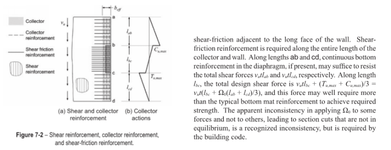
So for shear at side of wall there's two components. One is direct shear from diaphargm to wall, defined in NEHRP below as vutlbc, this component gets no overstrength applied. The other is any leftover shear from collectors that could not be deposited into wall ends, defined in NEHRP below as (vutlab+vutlcd)/3, this component would get overstrength. In buildings I've done we've almost always been able to justify collectors the same width as walls so the second component doesn't exist and thus no overstrength gets applied to any of the load at side of wall.

I think that means yes to overstrength on V1/V4 and V3/V6 when it gets delivered to wall (but not for diaphragm connection to collector). Same for V5. No overstrength for V2.

KootK said:
5b) Given the spirit of the related code provisions, I think that every damn scrap of tributary diaphragm load should get Omega'd at some point before it reaches the VLFRS. Anything less strikes me as diluting the desired margin of safety against the diaphragm tearing off from the wall before the designated energy dissipation kicks in.

So let's say we have a continuous wall along the entire right edge of the diagram below. If everything needs overstrength before getting to the wall then I need to design the dowels to the wall for overstrength?

----

Also, I don't think I'd generally apply any overstrength to the horizontal joint. There may be scenarios where I might need to, but generally I'd consider the load sufficiently collected and delivered to wall at that point.

If the argument is that the load isn't sufficiently deposited into the wall until below slab then that leaves me a little confused on what to do with shear load being transmitted from walls above. Those loads pass through slab too, are they not sufficiently deposited and thus also would need overstrength applied? Or is it just the component of load being delivered at each individual level that needs overstrength across this joint?

Capture_tdg2ju.png
 
Good to have you back in the pool MrH. Before we get going, I want to expand on my definition of a collector. I'll refer to it a few times so it'll be easier to just set it out:

KOOTK COLLECTOR:

a) for now, lets stick to collectors that are only as wide as the shear wall for simplicity.
b) collector includes drag bars in tension beyond walls. V4.
c) collector includes struts beyond walls. V6.
d) collector includes the long prism of concrete at the intersection of wall and slab. I concede that it is a special collector in the sense that incoming load may be envisioned to be sucked out of the collector as soon as it's introduced to the collector. See point #4 in my last post.

MrH said:
I'm not sure I completely understand the nomenclature or when overstrength is being considered on these loads, but I think maybe just V2 shouldn't get omega?

V2 = shear coming in along the length of the wall through collector bars outside the width of the wall.
V5 = shear coming in along the length of the wall through collector bars inside the width of the wall.

MrH said:
Essentially any shear delivered directly to side of wall from diaphragm gets no overstrength from me. Any shear that needs to be collected beyond the length of the wall gets overstrength when it's within the collector and when it's deposited into wall, regardless of whether it's deposited at ends of walls or if some ends up going into sides of walls (as happens if collector is wider than wall).

Excellent, it sounds as though I've understood your position accurately then.

MrH said:
overstrength on...Same for V5.

I'm surprised to hear you say that and I want to understand you perfectly so I'll confirm: you vote for over-strength on V5? That's the diaphragm shear delivered uniformly to the wall through the drag bars positioned within the wall width.

MrH said:
So let's say we have a continuous wall along the entire right edge of the diagram below. If everything needs overstrength before getting to the wall then I need to design the dowels to the wall for overstrength?

I almost posted this exact scenario as I consider it to be the extreme counter point example to my opinion. My thoughts:

1) this case, while interesting, is probably moot. Tons of wall and, omega or not, the connections can surely be made to work easily.

2) yes, even if it's moot, I do believe that it would be philosophically correct to apply omega to this condition. Obviously, my personal collector definition leads me to this conclusion.

3) I still view this setup as having a "collector" per point "d" of my collector definition.

Mr.H said:
Also, I don't think I'd generally apply any overstrength to the horizontal joint. There may be scenarios where I might need to, but generally I'd consider the load sufficiently collected and delivered to wall at that point.

In my sketches, I specifically used roof level detailing to emphasize this point. In detail A, at a roof joint, that horizontal shear friction joint is the last and most critical connection between the incoming diaphragm load and the wall. Is this one of the conditions where you would see the horizontal joint as being the connection between collector and wall? It certainly would be per my own collector definition.

Even at a floor joint, we agree that V4 is a collector and that its connection to the wall gets Omega treatment. If the horizontal cold joints are not the collector-wall connection there, what is for the V4 force? Surely if you have a connector joined to a wall, something has to be the "connection", right? Or are you seeing local bar development in the slab at the wall end as being the entirety of the collector-wall connection?

MrH said:
If the argument is that the load isn't sufficiently deposited into the wall until below slab then that leaves me a little confused on what to do with shear load being transmitted from walls above. Those loads pass through slab too, are they not sufficiently deposited and thus also would need overstrength applied? Or is it just the component of load being delivered at each individual level that needs overstrength across this joint?

This is going to take me further into what is really just my own interpretation of things for the most part.

4) When I'm considering the impact of walls above, I take the worst effect of diaphragm loads at the floor being considered and the VLRFS shear loads from that floor and all the floors above. Those are different loads owing to higher mode effects so it's not appropriate to use the diaphragm loads at all levels. This point is not in dispute but I though it best to table it for completeness.

5) Per the ACI clause on wall piers below, there will often be situations in the high seismic categories where you're applying Omega to the wall pier shear anyhow. I would certainly be applying the same loads to the wall-slab cold joints in shear friction.

6) In the lower seismic design categories, I will not apply Omega to the loads coming in from the loads above. This basically hearkens back to the "apparent" inconsistencies in mentioned in the NEHRP guide. I don't really agree with on a rational basis but applying Omega to the incoming wall loads would seem to put me out of step with code requirements and the practices of my competition.

7) Philosophically, I really see the walls as diaphragm collectors. They're vertical collectors "collecting" diaphragm loads from all of the floor levels and taking them to ground. It makes complete sense to me that they should get Omega treatment for shear as horizontal diaphragm collectors do. Of course, I don't really expect to change any hearts or minds on this point.

c01_d4j4l1.jpg
 
KootK said:
For communal review, I submit the sketch that is attached and shown below. This question has nagged so I wanted to summarize what I think we've learned here. Obviously, there are limits to my ability to know what folks other than myself have learned. All should feel at liberty to suggest corrections where I've gotten anything wrong.

I'll chime in to give you one more data point. From a code compliance perspective, I believe the NEHRP document and your interpretation of it to be correct. Philosophically, I agree that the overstrength factor should be applied to V2 and V5. As a compromise, our office amplifies V2 and V5 by 25%, which has some precedent in ASCE 7-10 12.3.3.4. This also keeps us from having to track any lateral system irregularities in our diaphragm/collector spreadsheets. If we have walls above, we'll add the design shear strength of the wall above (ΦVn) to the diaphragm/collector forces when checking shear friction on the horizontal construction joint.

I don't think your braced frame analogy is applicable here because the load is delivered to the braces at discreet points, making the entire beam line a collector and thus requiring overstrength.
 
Welcome.

Deker said:
If we have walls above, we'll add the design shear strength of the wall above (ΦVn) to the diaphragm/collector forces when checking shear friction on the horizontal construction joint.

Why the wall shear strength rather than amplified shear demand? Simplicity in tracking? This would seem more conservative than what I've been advocating.

Deker said:
I don't think your braced frame analogy is applicable here because the load is delivered to the braces at discreet points, making the entire beam line a collector and thus requiring overstrength.

That's sort of my point. I want to know what others feel is special about V2 and V5 such that it would justify their being treated differently from the other collector forces with respect to omega. Is it just that there is distributed connection between collector and shear wall beside those forces? Because that seems pretty arbitrary to me. The way that I see it is like this:

1) All six components of diagram force get delivered to the same, axially stiff collector trying to drag itself across the resisting wall.

2) I don't believe that it's even accurate to assume that load coming in beside the wall necessarily goes straight to the wall. I think that it just goes into the aggregated "pool" and may get redistributed up or down the line.

Hence my view of the non-special-ness of V2 & V5. I just see it as more load coming into the same pool. Since you mostly agree with me here, I realize that I'm probably preaching to the choir in some respects. Take my comments as being directed to the community at large.
 
KootK said:
Why the wall shear strength rather than amplified shear demand? Simplicity in tracking? This would seem more conservative than what I've been advocating.

Yes, simplicity in tracking is one reason. Would also like to keep sliding failure along the joint lower than wall shear failure on the hierarchy of preferred limit states. It shouldn't be much more conservative than designing for the amplified shearwall demand provided the shear capacity doesn't far exceed the amplified demand. In my experience for flexurally controlled walls, the demand capacity ratio for shear is usually pretty close to one.

KootK said:
Is it just that there is distributed connection between collector and shear wall beside those forces?

Yes, I believe that is the fundamental difference used to justify not amplifying the load. Right or wrong, distributed connections are perceived to have greater redundancy and inherent overstrength when compared to discreet connection points on a collector line. This is the logic used in the seismic chapter of the Bondy & Allred PT book when they choose not to amplify the diaphragm forces for the slab to wall dowel design. Again, I don't fundamentally agree with this, but it does appear to be the intent of the code.
 
Status
Not open for further replies.

Part and Inventory Search

Sponsor