Eng-Tips is the largest engineering community on the Internet

Intelligent Work Forums for Engineering Professionals

  • Congratulations waross on being selected by the Tek-Tips community for having the most helpful posts in the forums last week. Way to Go!

Collapse pressure of steel casing 1

Status
Not open for further replies.

MarioGr

Structural
May 28, 2014
28
0
0
AU
Probably have been done to death here but after reading numerous threads and googling the hell out of it and consulting Roarks I am none the wiser so here I am.

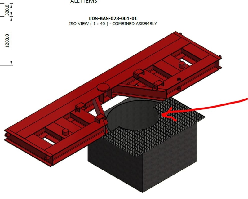
I have a drilling client working out woop woop in Australia. (It's near 'Out to Buggery'.) They will dig a hole some 2.0m x 2.0m and drop a 1800mm diameter casing that is 1200mm deep with an 8mm wall into that hole. They will then backfill and compact against the casing on all sides. (Possibly using a high slump mass concrete mix which is neither here nor there.)

Here's the important bit. They will then place a drilling sub-base immediately adjacent the hole/casing. That sub-base when fully loaded with the drill rig in position will exert a surcharge loading to the soil under of 130kPa.

With a soil friction angle (Ka) of 0.33 I get a lateral pressure to the casing of 43.3kPa due to the surcharge.

Ignoring the soil conditions, whether it was compacted evenly around the circumference , whether the subbase is exerting a UDL is there a formula that you can calculate to work out either the required thickness of the wall required or the collapse load of the casing?

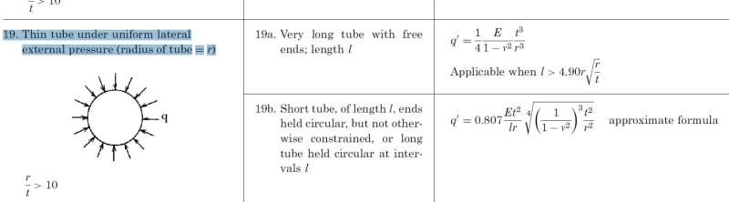
The Roarks formula I have seen here posted previously is for long thin walled tubes. The D/t ratio for this casing exceeds the parameters of the formula they use.

Do I just calculate the hoop stress or is it more involved?

Would someone be kind enough to help? Thanks in advance. (Red arrow points to casing. Floor grating over half of casing.)

Capture_2_mgye0s.jpg
 
Replies continue below

Recommended for you

The issue I have with this is that your external pressure will vary as you go down - virtually nothing at the surface increasing as you go down, whereas all these calculations assume a fixed pressure all the way along the tube.

Also what is at the end of this tube? Does it just sit on top of some blinding or is it actually pushed into the ground and hence provide some resistance to the external forces. If not why not?

But is this important or just for curiosity? If it bends a bit then so what?

Have they built these and they are collapsing or??

8mm on 1800 though is a D/t of 225. Basically that won't stand any force, especially a point load or over a certain portion of the radius.

I've seen these initial wellhead casings go in using corrugated tubing and they worked just fine.


Remember - More details = better answers
Also: If you get a response it's polite to respond to it.
 
If I understand correctly, I think "using a high slump mass concrete mix" will behave far better than the Ka of compact sand. The casing is simply acting as formwork for the concrete mix. Is it not.

 
Ignore the concrete. There's no quality control out there. We're literally talking middle of a paddock 80 - 100 kms from anywhere. It could be concrete it could be dirt.

Forget all the variables and just imagine a casing in a hole with a surcharge loading. That surcharge loading is imparting a lateral load. How do you calculate what capacity does that casing can take. Ignore whether it's pushed into the ground and supported at the base. It probably will be but for the exercise assume no restraint at either end.

Thanks for your interest.
 
How do you reply to specific posts?

On occasion a worker will have to drop into that hole to do work. I need to know that that casing will not collapse on him due to the surcharge loading.

Thanks
 
If this is being put in by a pile contractor (I'm not clear what exactly is going on here).....why is the casing design on your plate? I've never had a pile contractor ask me for a casing thickness. Typically they've got a bunch they re-use.

But to answer your question, Roark's formulas are what I would try as well.

Another resource could be state DOTs (here in the USA)....here is one from Iowa (see Table 1):


If it was being driven in.....that's a whole other animal.
 
If this is a casing to protect people, be conservative. Also note that for something like this although uniform pressure is the ideal scenario, it's more likely to have concentrated type loading in some areas where the compaction is well done and bearing uniformly against the sleeve, and there will be areas where the compaction is inadequate and applying signficantly less pressure. So you won't benefit from the even pressure on all sides.

8mm on 1800mm does seem thin to me as well. On casings of that diameter for sewer work temporary shoring around here they're closer to 19mm thick, and depending on depth of application have regularly spaced stiffener rings.
 
I have used your 19b formula for vertically installed pipes in soil and water. I see no reason that it cannot be used for a nonuniform distributed load. Design for the unit foot of length that has the highest load, or do the same in each of several load bands of your choice. The problem will be that it will require higher D/t ratios than you might like. A potential problem with the formula, if any, is that it is for an infinitely long cylinder. Nearby edges may reduce the resistance. One way to compensate for close end effect might be to add ring stiffeners at the edges.

Personally I dont believe quality control of the concrete is an issue. I certainly wouldn't lose any sleep over that, as the casing is still in place. Neither is 1200mm depth of all that much concern for personnel entry, unless they are lying flat on their backs. I fail to see any reason to get excited about this.

 
The casing has been fabricated in a workshop and taken to site. There's no piling. They are literally dropping it into the hole. It's only 1200 deep.

It's landed on my plate because I certify a bunch of other equipment for these blokes and the head contractor has asked the boys on site for certification of the casing and so here I am.

I realise the pressure won't be equal on all sides at all places. But what do you do? You have to idealise it and add a fairly hefty factor of safety.
 
@1503-44

Thank you. I have used the formula and I'm getting a capacity well in excess of the design load. I'd love an opportunity to confirm that via another method as I don't have a 'feel' for what is a realistic value using that formula. IE could be a case of garbage in, garbage out.

Anyway gents it's 1.30am in Oz so I'll check back tomorrow morning after I get some Z's.

Thanks again.
 
"How do you reply to specific posts?" - Only by referring to the author and if necessary the date and time stamp. That's just how it works on this site and stops you getting nested posts.

I do understand what you're trying to do and why, but don't think when you find the answer you can do much with it.

If you want some level of FoS, then you should be adding stiffener rings or angle at 500mm intervals, using corrugated pipe or adding cross bracing at the bottom level, but then I guess the Christmas tree / BOP is in the way.

Like I said, if you assume a constant external force then you're being rather conservative and if not then you might find it difficult to get an answer.

Maybe try looking at this as though its a buried horizontal pipe, 1.8m deep and you run a large load over the top of it.

If you look at API RP 1102 for casing pipe under roads or look up spangler and Iowa pipeline calculations you'll probably be able to adapt your case to this. Then add a safety factor of your choosing.

CEPA have done a lot of work on crossing of large agricultural vehicles over buried pipelines and there are many online calculators.

You will probably need a thicker pipe.

Remember - More details = better answers
Also: If you get a response it's polite to respond to it.
 
The only part that I am concerned about is the top edge. Stiffener rings may be the best bet.

= = = = = = = = = = = = = = = = = = = =
P.E. Metallurgy, consulting work welcomed
 
There isn't a great way to calibrate how a heavy vertical vehicle load corresponds to lateral earth pressure. In any case that would more likely result in much higher thickness anyway.

Mario, Your answer is probably correct. Its not all that easy to collapse a pipe, even with a high D/t and with full load of 1.2 meters of soil on it. Additionally, what really helps pipe resist external loads, especially a horizontal pipe with a heavy vehicle load above, is actually not just having a small D/t ratio, but how well the pipe is supported by well compacted soil on either side that keeps it from buldging outward at the sides and flattening from the increased "span" of the ever widening and flattening pipe. As the circle becomes a horizontal oval, the "arch" gets ever wider, increasing the span and the resulting with high bending moment in the pipe wall. It eventually caves in as the distance between the side walls increases. If the side walls are prevented from moving apart by well compacted fill on either side, basically the arch will remain strong and it won't collapse until it fails locally at the top of the arch which requires a far greater load to do that.

And, in this situation, you are not talking about total collapse of the pipe. It won't flatten leaving a vertical pancake. The walls may bend or bulge in somewhat, with a localized buckle, but the basic shape of the pipe will not change. It is really as such, a self-limiting event. Humpty Dumpty will not die and be crushed to smitherenes in a submarine-like hull crushing failure.
 
For only 1200mm of depth, I'm surprised it's required at all if it's just retaining soil. Around here, you don't need shoring until the excavation exceeds 1200mm.
 
It may be needed for frequent or long term access.

Rather than think climate change and the corona virus as science, think of it as the wrath of God. Feel any better?

-Dik
 
@ jayrod12 Over here it's generally 1500mm before shoring is required although you can go deeper if you bench out 1.5m for every 1.5m you go down. (To a point.)

The reason for them asking for certification is these massive mining companies the drillers are working for are hypervigilant when it comes to safety. I mean you should see some of the silly stuff I have to issue a certification for. Move a cleat 100mm from where it was - certify it, add a cleat to lift say 1 tonne that's 20mm thick and 200mm wide - certify it.

Doesn't worry me, I get paid for every piece of paper I issue.

In this instance the chances of a catastrophic failure are next to zero but I do wonder how how would calculate the collapse pressure if it were 5.0m deep or 10m or 20m. Or that casing went 30m down into a dam and had the water on the inside pumped out. There must be a way?
 
Status
Not open for further replies.
Back
Top