Continue to Site

Eng-Tips is the largest engineering community on the Internet

Intelligent Work Forums for Engineering Professionals

  • Congratulations waross on being selected by the Eng-Tips community for having the most helpful posts in the forums last week. Way to Go!

Column Base Moment Connection

Status
Not open for further replies.

Serhiy2

Civil/Environmental
Nov 10, 2018
44
Good day,

I'm working on addition of crane in the existing shop that has 6" slab on grade floor. I will be using cast-in-place piles for crane support columns. One constraint I have is that I don't really have anything to tie into to resist lateral forces caused by crane operation (forces perpendicular to crane runway beams). The only element where I could put some forces is roof diaphragm but I don't want to put much into it.

Making column base connection as moment connection does help but involves many-many anchors. My column base plate will sit below the slab so I was thinking of relying on lateral force resistance by slab working in pair with regular column base connection to produce some moment resistance.

One concern I have is about the rigidity of this slab resistance deteriorating with time after many cycles of loading. I'm basically looking for some feedback on this idea as I'm sure many of you have considered/used this approach before.

Thanks
 
Replies continue below

Recommended for you

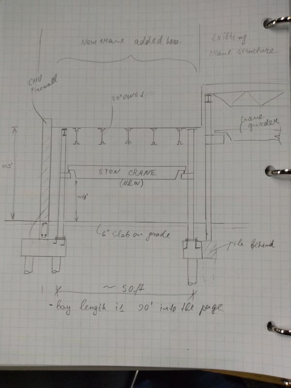
It sounds like you are designing support system for overhead runway crane, and concerned with the lateral thrust produced by the trolley movement. Can you show a building cross section?
 
IMG_20200111_175116833_xk6fo8.jpg


Please let me know if any other info is needed to better understand the situation.
 
Is this a new building addition? Or adding crane only? How much is the lateral thrust you got? How much space is available between the CMU wall and the column, and between the existing and new column in the middle?
 
It's adding crane and firewall only. Lateral thrust is 4 kip total (2 per side). I have 3" between left column and firewall and 6" between right column and existing framing.
 
I don't see any reason why the slab couldn't be assumed to provide lateral resistance. As long as the base plate anchorage and edge distance, etc. of the footing are sufficient to resist the shear applied to the base plate.

Rod Smith, P.E., The artist formerly known as HotRod10
 
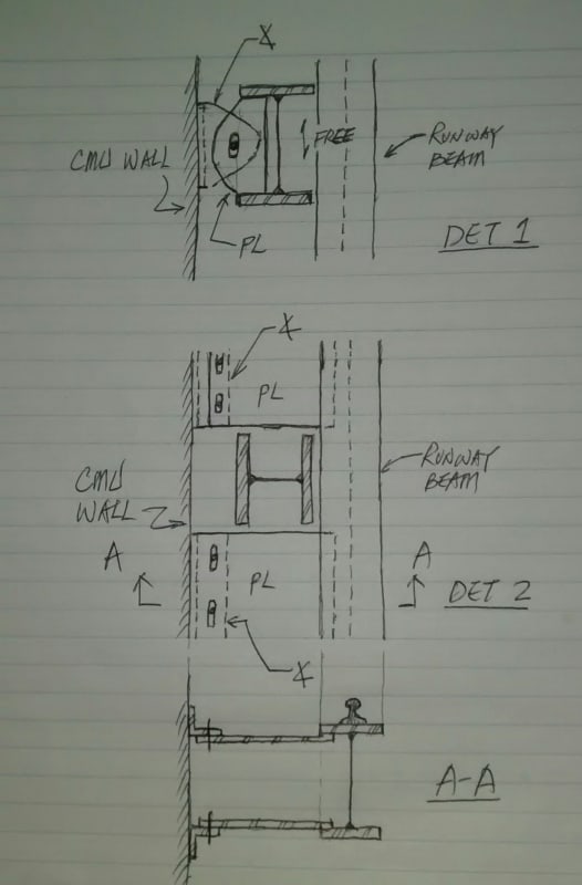
I suggest to provide CMU/concrete bond beam at the runway beam level, and provide ties that is capable of resisting the 4k lateral thrust. The tie shall consist two pieces, one on wall, and one on column. then connected by bolts through slot holes.

Is there any reason why you can't bring the pile cap to the floor level?
 
Retired: not sure attaching to the cmu creates any better of a load path, but if detailed properly could work.

The slab on grade might be able to be utilized for the lateral resistance but make sure you carry that load path to conclusion and verify enough sliding resistance and capacity. Also need to make it clear that the slab is stabilizing the structure so future work gets coordinated to not remove large portions of the slab.

Open Source Structural Applications:
 
It just to take out the lateral load, if the wall is stiff enough, instead of messing with difficult moment connection at the base, yet still produce large deflection at the runway level.
 
I can't quite read the vertical dimension on the left, but it looks like you may have clearance to use a rigid frame, crane columns and a beam above the crane. I would depend neither on the slab or the masonry to provide support laterally.
 
Ideally, it should have a backup truss, but then the wall needs to move farther away, as for now, there is only 3" space between the column and the wall. The wall needs to be reinforced both ways in order to be effective. For 5 ton crane, 4 kips lateral seem a little too high though.

I think the dimension to the roof is 20.5', and wall height approx. 22'.
 
Serhiy2,

Forgot to mention one thing. Before pin down your design, check to see what is the configuration of the bridge end truck wheel - flanged on both sides, or one side. If one side, is on the inner rail side, or outer rail side? The one side type has more tolerance on rail misalignment, but obviously will affect the distribution of lateral thrust, therefore, your design layout.
 
retired13,

Thank you for all your input. I was trying to avoid connecting to firewall as it needs break-away connections. Also, there is office mezzanine/2nd floor on the other side of the wall and putting the lateral force in the wall might result in vibrations reaching the office structure. I will check what it would take to be able to use slab on grade to provide base moment resistance.

 
Understand your situation better now. I'll suggest:

1) Select a stiff column to minimize lateral deflection at the runway level.
2) Consider use shear key to take out shear force, and let the anchor rods to resist tension.
3) Provide braces in frames supporting runway rails, eliminate the need of moment connection at the base in that direction.

I think for a 5 ton crane, the measures above should be adequate to take care of the problems. You may consider utilize the concrete floor to provide resistance, just beware the details around the interface, as the column will vibrates and swings under the moving load, and the concrete slab tends to shrink away, and cracks.

You didn't answer my question, "
Is there any reason why you can't bring the pile cap to the floor level?
". By doing so, the column will be shorter, and won't need protection for soil.
 
hokie's idea of a rigid portal frame seems viable to me.

What is the lateral force resisting system for the bridge crane in the existing bay? Could you tie the new framing into the old framing to piggyback on the existing LFRS? Maybe lattice the columns together. In conjunction with a portal frame, that could stiffen everything up considerably and reduce sway.
 
I agree with Hokie66, the moment at base and anchor loads can be too much plus you will have stiffness problem in the frame. A rigid moment connection, either by beam-col joint or better a brace between a beam above the crane and col would be efficient and more stiff for lateral loads and sway.
 
Serhiy2,

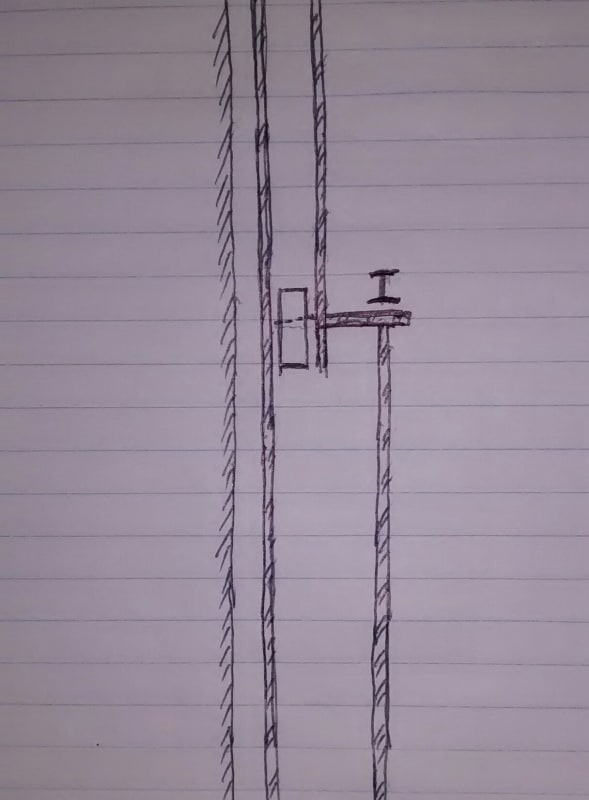
If you have headroom constrain for portal frame, here is one strong column option for your disposal.

c1_yxqwpy.jpg
 
1) I see some suggestions ref tying columns back to CMU wall.. we will NOT do this.. These tie backs experience dynamic & reversing loads... will cause cracks in CMU.
2) Someone mentioned 4 kip lateral load - This is way high for common 5 ton crane... assuming 1000# hoist....
11,000 (hoist & load)
x .2 (per AISC & ASCE)
x. 5 (1/2 of load to each side)
x approx. .925 (one ET wheel is over column, other wheel is XX ft towards next column down the runway)
yields 1,018#

3) This is the lateral force a free standing column & foundation will be designed for
I suspect things just got a bit simpler & smaller
But still DO not tie back to CMU wall
unless its a CMU double block column WITH rebar & full pour

4) Many commercial CMU wall buildings Ive seen have a double block & poured column on regular intervals along length of wall

We use simple W beams for this with runway beam simply bolted to top of column - no portal frame needed if there's a foundation being poured.
there have been shares of a spread sheet on this forum that sizes foundations with axial & moment loads
this is of course a moment loaded column


Serhiy2,
I don't know the distance between the short and long col on the right side of your sketch, bigger better, if they are aligned, you could tie them together with beams as moment connection and/or cross braces to resist lateral load from both cranes. Base anchors will have less tension due to wider foot print of two cols. Just a concept not sure about numbers.
 
Status
Not open for further replies.

Part and Inventory Search

Sponsor