Continue to Site

Eng-Tips is the largest engineering community on the Internet

Intelligent Work Forums for Engineering Professionals

  • Congratulations cowski on being selected by the Eng-Tips community for having the most helpful posts in the forums last week. Way to Go!

Column Beam Concrete Connection 2

Status
Not open for further replies.

SteynvW

Civil/Environmental
Feb 1, 2016
108
Conncection_kkx3mt.jpg


Hi All

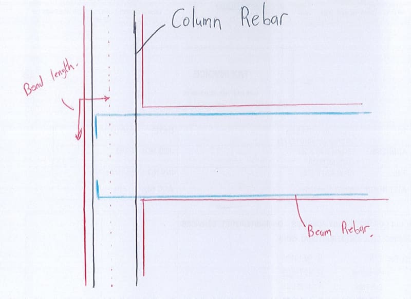
In the attached picture is a concrete column and beam connection. For the beam design
moments at the end will be ignored and the beam designed as a pinned support at the column.
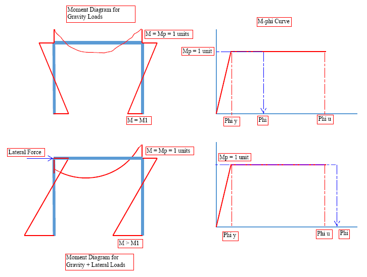
For the lateral stability, can the negative moment that will be generated/developed by the top reinforcing
over the bond length from the tip of the reinforcing to the center line of the column be used for lateral
stability?
 
Replies continue below

Recommended for you

Yes, you can do that, as long as you provide negative reinforcement according to the demand of the lateral case. However, you should anticipate to see cracks across the negative moment regions, if the negative moment demand of gravity load case is greater than the lateral.
 
Any reason for treating it as pin? I would have expected it to be treated as a frame.

"Programming today is a race between software engineers striving to build bigger and better idiot-proof programs, and the Universe trying to produce bigger and better idiots. So far, the Universe is winning."
 
you should anticipate to see cracks across the negative moment regions

these cracks however should be very small if the beam is designed as pinned support and thus stiffer as it would
have to be a deeper beam to satisfy the rest of the requirements. Is this correct?

Any reason for treating it as pin? I would have expected it to be treated as a frame

If the reinforcement is detailed as per sketch with a standard hook (100mm length) and if the column is not very wide then it will not
be able to fully develop to transfer moment if my understanding is correct
 
I concur with your approach of reinforcing the end span for gravity loading as if the external support is pinned. And also would provide reinforcement at the top at that external column for in the order of 1/2 the gravity moment at midspan. A standard hook is fine, but 100 mm is too short. That would depend on the bar size.

If you are using a rigid frame for lateral loading, that is a separate load case.
 
hokkie66 said:
If you are using a rigid frame for lateral loading, that is a separate load case.

Yes, I am just using a rigid frame for lateral loading. As the detail above will probably not give full moment transfer, only partial
I am just looking at a way to quantify how much will/can be transferred.
 
I've only got the time to upload this picture. I'll explain what I've drawn once I get free.
Case1: Assuming the provided top reinforcement is developed
If you have provided even smallest of the reinforcement on a tenaion face then it will resist the moment due to gravity loads upto the provided capacity. Once this capacity, Mp, is reached then it will distribute the remaining moment to the bottom of the beam. Your assumed pin type behaviour will be achieved when the provided steel has started to yield. If you've provided sufficient ductility then your curvature could be anywhere between the ultimate and yeild curvature (as shown in fig. in the top right corner).

Now, if you apply a lateral load on this frame with beam ends already yielded, then the beam-column joint will not be able to take up the moment more than the capacity of the beam i.e. Mp and will distribute the rest towards the support. In the mean while the top reinforcement of beam at support will continue to yield due to the lateral load and may even reach or surpass the ultimate curvature (as shown in fig. in the bottom right corner).
This will result in sudden strength reduction due to either, concrete crushing or, rupture of tension steel.
Of course there's a possibility that, the curvature of beam might not pass the ultimate curvature. This will depend on the magnitude of the applied lateral load.

Case2: Assuming the provided top reinforcement is not developed
If the top reinforcement is not develope then the joint will act like a pin for a gravity load. When the lateral load is applied, beam will not provide any rotational resistance, it will only help in dividing the lateral load between the n number of columns in the frame. And column will act like a cantilever with load at it's free end.

image_pgmtp1.png
 
OP said:
these cracks however should be very small if the beam is designed as pinned support and thus stiffer as it would
have to be a deeper beam to satisfy the rest of the requirements. Is this correct?

I somehow been able to grab your argument, the answer is "yes", and "no". Yes, the cracks could be finer because of the extra positive moment capacity. No, because the help (from positive moment reinforcing) is minimal. Even you are in doubt whether the beam column joint is capable of develop full negative moment due to perceived joint rotation, this joint is still much stiffer than the concrete member in the mid-span. When loaded, the force tends to be drawn to the most stiff region, and the other region will feel the force/stress only after the most stiff region failed to resist the force alone, and have to distribute it to the other region to maintain structural equilibrium. In simple words, if the negative moment region does not crack, the positive moment region may not see/feel much force/stress. Therefore, if you provide negative reinforcement less than the amount called for by the gravity load case, the mechanism will go like this - the negative moment region cracks, and rebars yield, as the crack widens, the beam curvature increases, then the positive moment reinforcement will now be dragged into play to maintain equilibrium. This phenomenon is better explained in text on "plastic design" method, if you want to know more.

It looks like your are trying to justify the use of two different models - one for gravity load, one for lateral load, to simplify your design. To me, it can cause confusions and omissions. Try to be consistent.
 
Thank you Blackstar and Retired.

Just to take it one step further, I see a lot of buildings in my area that are 3/4 storeys high
that flat slabs (no beams) that have no apparent lateral load resisting system (no shear walls, no elevator core).
This is however not a seismic zone.

Is it even possible to create a moment frame for lateral stability between a flat slab and columns?
Out of interest I built a simple model and if there is no moment transfer (between the slabs and columns)
and I perform a second order analysis your columns would need to be massive.
Unless I am missing the plot completely
 
I don't think you are missing the plot, but the designers of those buildings probably did.
 
You sure they didn't have torsion beam in the slab? Otherwise it is a stretch

"Programming today is a race between software engineers striving to build bigger and better idiot-proof programs, and the Universe trying to produce bigger and better idiots. So far, the Universe is winning."
 
Status
Not open for further replies.

Part and Inventory Search

Sponsor