Continue to Site

Eng-Tips is the largest engineering community on the Internet

Intelligent Work Forums for Engineering Professionals

  • Congratulations SSS148 on being selected by the Eng-Tips community for having the most helpful posts in the forums last week. Way to Go!

Column Buckling Analysis 1

Status
Not open for further replies.

JohnnnyBoy

Structural
Oct 13, 2015
81
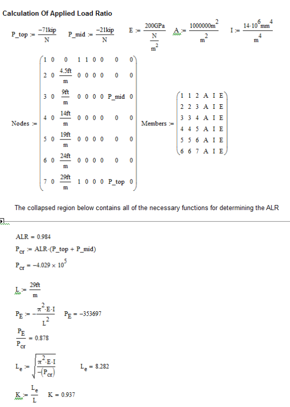
I'm designing a catwalk system that will be installed into a new building. Basically the building was previously designed and I'm trying to calculate the buckling of the column. The height of the building is 29'-0" Tall and the height of the catwalk is 9'-0" Tall. The load from the roof is 71 kips and the load from the catwalk is 21 kips. The catwalk does not provide stability or restrain as it is kinda like a tree stand of sorts and is supported solely by the column.

Basically for the purpose of my design I designed the column as if the entire 92 kips was acting at a height of 29'-0" although I am aware this would be over designing the column. I tried to model it is Etabs as well although I do not think there is a way to model it as it considered the two columns as being separate or it would not allow me to add a load a certain distance down into the column. I do believe SAP2000 has this capability although I do not have the program. Does anyone have any design manuals for this sort of calculation or any insight on how I should be designing it/

Thanks in advance.
 
Replies continue below

Recommended for you

Most column design assumes a constant load for the column along the unbraced length. However, there are techniques for analyzing columns for variable loading along their length.

AISC has a design guide on tapered members that has a method for doing this. They use it (obviously) because the member properties may vary along the length. But, the same concept can be used when the load varies. See Appendix A for the "method of successive approximations" or Timoshenko and Gere (1961) and Newmark (1943).

Not that difficult to do today with Excel spreadsheets making it so much easier.
 
From the "tree stand" analogy, it sounds like you would potentially have quite a bit of eccentricity in the load, and that should be considered as well.
If you're in a seismic region, you'd pick up some seismic load as well.
You may also have some adjustments in base plates, anchors, attaching structure.
 
I think that your approach of assuming all of the load to be at the top of the column is what most engineers would start with. Does it not work out that way? You might get a little bump by considering some of your load applied mid-height but, based on your load split, I doubt that it would be much. Probably not enough to justify the extra design effort.

Timoshenko's book on elastic stability covers a case where the load is distributed along the entire column length uniformly. That would be unconservative for you but would allow you to bound your problem and decide if it's worth the effort to get any fancier.

To my knowledge, none of the common software packages would allow you to properly do simple, linear elastic model, code checks on a column of this sort without some massaging. The only way that I can think of to fudge it would be to calculate an equivalent K value by hand and then manually input that into the design checks. I've got a MathCAD spreadsheet that I set up to calculate the equivalent K value. If you're interested, and have MathCAD yourself (v15), I can share that. It's not well documented, however, and relies on a bunch of matrix/eigenvalue voodoo. I'm not sure that you'd ever be willing to trust it for your own, real world work.

Of course, if you're using a software model based on second order analysis method like the Direct Analysis Method, then the software certainly could be used to evaluate stability.

I like to debate structural engineering theory -- a lot. If I challenge you on something, know that I'm doing so because I respect your opinion enough to either change it or adopt it.
 
Yes in my case I would get a lateral force being applied to the column at the catwalk connection from the bracing. The location would be Alberta so there is no major seismic loading. Base plate and anchors are designed for tension forces due to the lateral force. Josh, thanks for the reference I will give it a read.
 

Complex analysis questions like this are frequently interesting to me. So, I delved into them at times in the past and am happy to share knowledge or resources.

However, it probably is a good idea to caution (as KootK does) that, while I consider this a fascinating academic exercise, it may turn out to be much ado about very little difference in behavior. While it isn't that difficult you probably still would be spending a day or two to make sure it's right. Then you'd have to compare it to what you get by your simplified method to see if the time earned you any extra capacity or not.
 
Thanks everyone! I do agree with both of you that a simplification may be the best way to move forward as a second order analysis may well give me a similar answer. Thank you for the offer of the MatLab spread sheet although I think for something complicated like that I would need to go through it completely myself to ensure that i'm not missing anything for my particular design. I did draw up a quick FBD and drawing. With the tree stand type design it does create an internal moment at the connection. The designed beam can handle the internal moment but I just want to ensure it would not effect the buckling load of the column.
 
 http://files.engineering.com/getfile.aspx?folder=f5a2936e-5b3f-42ef-bf1f-7e57a099fcd6&file=20170125125619.pdf
JohnnnyBoy said:
The designed beam can handle the internal moment but I just want to ensure it would not effect the buckling load of the column.

The transverse loads applied to the column definitely affect buckling. Normally, however, we take account of that by simply using the beam column procedures in the code.

JohnnyBoy said:
Thank you for the offer of the MatLab spread sheet although I think for something complicated like that I would need to go through it completely myself to ensure that i'm not missing anything for my particular design.

My widget gives KL = 0.94 X 29 ft. So about a 12% increase in axial capacity. Pretty modest.

Widget_apngbb.png


I like to debate structural engineering theory -- a lot. If I challenge you on something, know that I'm doing so because I respect your opinion enough to either change it or adopt it.
 
The second sheet indicates that the column is fixed at the base and roller supported at the top with the note "not fixed in Z direction". It seems to me that is equivalent to being fixed at the base and free at the top, i.e. a pure cantilevered column.

Edit: I believe the intent is that the roller is free to roll in a vertical direction. Then everything works fine.
 
BA yes that was the intent.

KootK thank you for the insight, I followed through with the beam column calculations and everything was good and used your matrix in calculating a more precise K value which as you mentioned slightly did increase the axial capacity.
 
You're most welcome. Albertan solidarity in action. I don't run spreadsheets for just anybody.

I like to debate structural engineering theory -- a lot. If I challenge you on something, know that I'm doing so because I respect your opinion enough to either change it or adopt it.
 
Status
Not open for further replies.

Part and Inventory Search

Sponsor