Continue to Site

Eng-Tips is the largest engineering community on the Internet

Intelligent Work Forums for Engineering Professionals

  • Congratulations KootK on being selected by the Eng-Tips community for having the most helpful posts in the forums last week. Way to Go!

COLUMN COLUMN STEEL CONNECTION THROUGH EXISTING SLAB

Status
Not open for further replies.

NAFTALI-HAKOHEN

Civil/Environmental
Apr 8, 2021
26
HI ALL

IM DESIGNING A STRUSTURAL REFURB TO AN EXISTING CONCRETE STRUCTURE,

WERE SUPPORTING THE EXISTING STRUCTURAL ELEMENTS , BEAMS COLUMNS, WITH STEEL FRAMING,

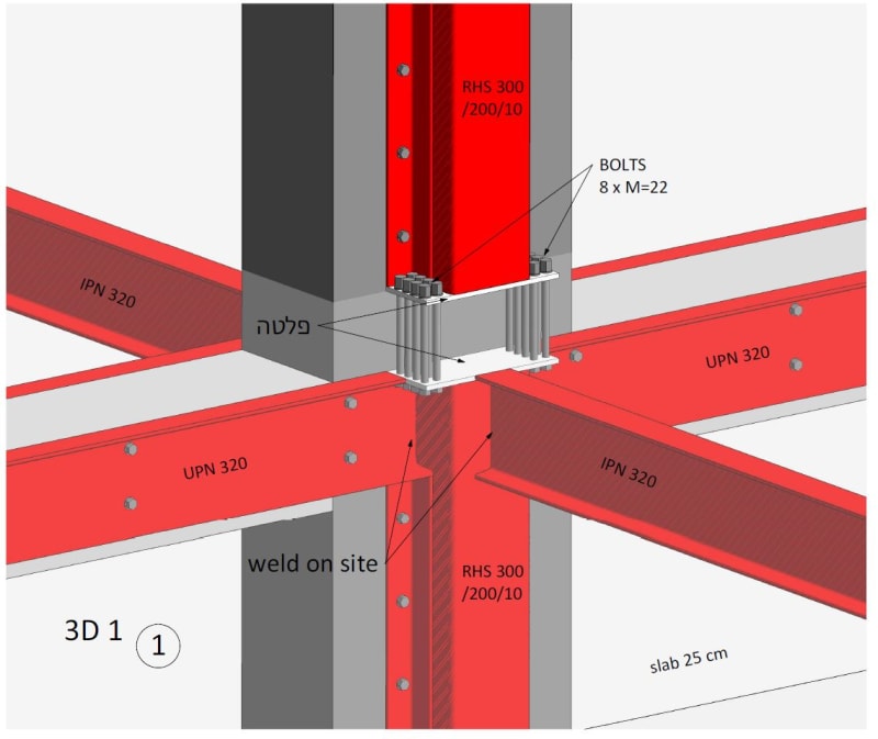
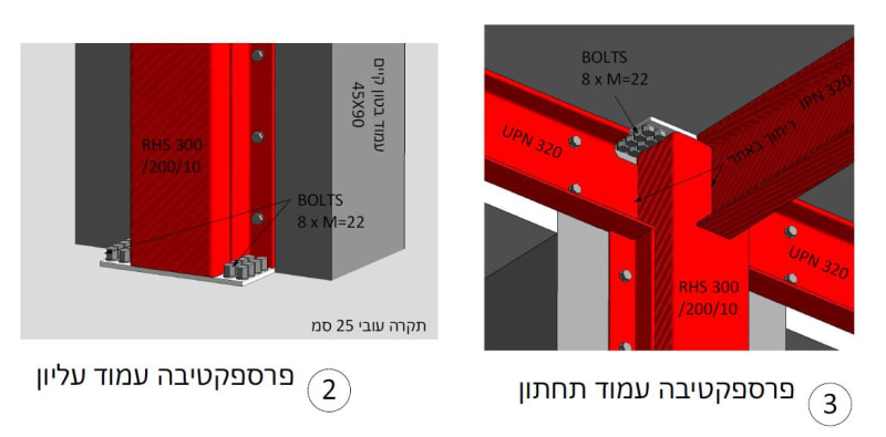
SPECIFICALLY HERE , MY BOSS WANTS A CONTINUITY OF MOMENT THROUGH THE NEW STEEL COLUMNS, THAT ARE POSITIONED ABOVE AND BELOW THE EXISTING SLAB,
%D7%9C%D7%9B%D7%99%D7%93%D7%94_dittqi.jpg
%D7%9C%D7%9B%D7%99%D7%93%D7%94_xztyqp.jpg


IVE PUT A STEEL PLATE, WITH 16 BOLTS THAT ARE DRILLED THROUGH THE EXISTING SLAB,

WEVE GOT MOMENTS OF AROUND 13 TM AT COLUMN BASE - TRANSFER,

WOULD LIKE SOME THOUGHTS ON THIS RATHER ORIGINAL CREATION!

NAFTALI
 
Replies continue below

Recommended for you

Absolutely 0 dice to be had on that connection.

I see a number of problems

1) For structural steel those holes can be no bigger than 1/16 than the bolt size. Lining up 16 bolts to 1/32 tolerance (1/32 per side of the bolt) across the slab depth is a heroic effort.

2) Even if you manage to be a hero or use alternatives (such as welded washers on one side which is how we typically deal with through-bolting existing concrete) you now have 8 bolts in such close proximity that there's going to be 0 concrete left (which also poses a problem for drilling since bits will wander and go into adjacent holes). The 0 concrete left means your bolts are in bending across the depth. That won't work for a 13 knM moment.

Solutions

1) Chip a pocket near the column and insert a bypass member through the slab. Weld as needed top/bottom. Cast back in-place as required. Include for repair of rebar as needed or chipping a larger area to add rebar to the side of member (use welded splice to reduce removal extents)

EDIT - Note that my solution likely requires you to get comfortable with moving any bar near the face of the column if it exists (probably does but a scan would be prudent prior to design). But that's life in the big city as they say and would similarly be a problem with the mountain of anchors coming down either side.
 
hi,

thanks for that,

i hear the issue with the lining up,

with regards the concrete drilling, the plate width is 20cm, and i have 4 bolts of diameter 22mm along this side, leaving around 2+ cm space between each bolt, will that leave no concrete between them?

im not sure i understand your solution...could you sketch something? are you suggesting to make a say 10*10 hole in slab on both sides of RHS and feed an element through and weld it to top and bottom columns?

the basis of my connection design philosophy in this case was to do minimal damage to existing structural elements i.e not to change load paths etc, just to provide an alternate load path in case something fails (seismic etc) , and im not sure huge holes in slab fits with that.

theoreticlly, if the bolts dont go entirely through the slab, can i rely on the old aged concrete to provide the integrity neede to allow moment to transfer from the upper to lower column? thats the real question here

the moment is 13 tm or 130 knm,

thanks
 
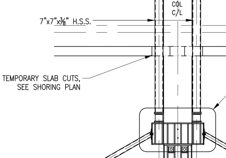
RE: my solution that is correct. I would vastly prefer a member that goes entirely through the slab. I recently did something similar on a shoring project and while temporary it's close enough as a concept (though you'd have moment connections top/bot instead of jacks)

Pic1_feij7q.jpg


You have a bit more concrete than I originally thought to be fair, but it's still not great especially when you consider you'll need to oversize the holes for constructability. And that leads to issues of potential bending inside the holes under the slightest bit of movement. Unless you grout them but then I would think the grout plane would be critical since it would be the stiffest path. Also, 100% you run into rebar interference where you want to put some or most of the bolts as well (EDIT - same issue as my solution so I dont know if much advantage on that front).

I don't know. Lots not to like about the bolts. Maybe a pedestal that helps get loads down might be the way to go. Let me ponder a bit.

Hopefully someone else can add here.
 
How about this: why do you want full flexural continuity through the column joint? Once we understand your goals, we'll be in a better position to help you achieve them.
 
OP said:
the basis of my connection design philosophy in this case was to do minimal damage to existing structural elements i.e not to change load paths etc, just to provide an alternate load path in case something fails (seismic etc) , and im not sure huge holes in slab fits with that.

Those gaggles of bolt holes through your slab are going to compromise the slab's shear capacity right where you need it the most.
 
NAFTALI-HAKOHEN ,


The use of RHS 300x200x10 is not a good idea.. I am not sure for the width of the existing RC beam (450 mm? )My suggestion will if the beam width around 300 mm, use 4 ea. unequal Angle L 200x100x15 at corners , if beam width 450 mm, use 4 ea. rectangular flat bar 150 x 25 .

The four profiles will be continuous and connected with batten plates.

When you write (Strengthening of RC Buildings with Steel Elements) and search the web, one of the outcomes

Probably strengthening with Steel Elements is not the best alternative ( others jacketing of columns, adding new RC shear walls..).. If you post the plan of the bldg , you may get better responds..
 
Status
Not open for further replies.

Part and Inventory Search

Sponsor