Continue to Site

Eng-Tips is the largest engineering community on the Internet

Intelligent Work Forums for Engineering Professionals

  • Congratulations SSS148 on being selected by the Eng-Tips community for having the most helpful posts in the forums last week. Way to Go!

Column design with eccentric beams

Status
Not open for further replies.

kellez

Civil/Environmental
Nov 5, 2011
276
Hello everyone,

I am designing a 2storey RC frame house according to EC2 and EC8 and three of the columns are impossible to design.
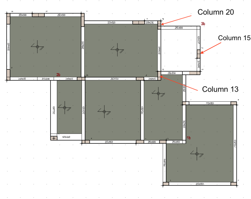
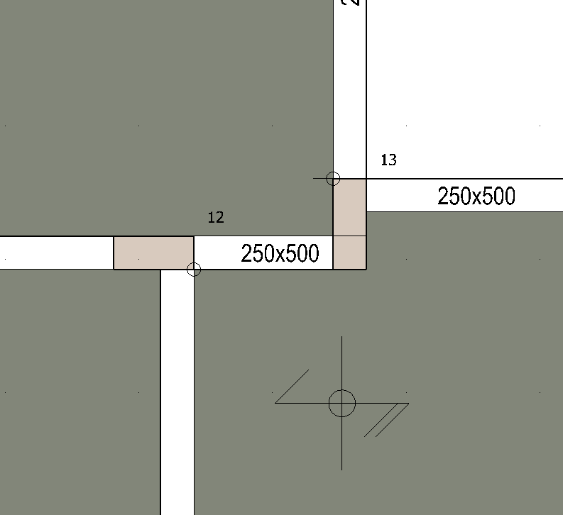
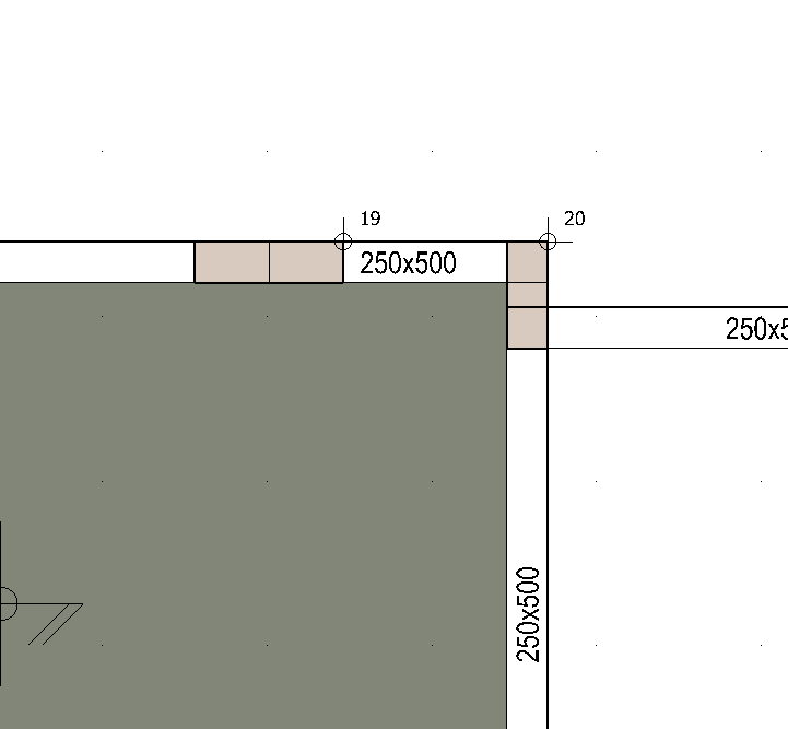
Two of these columns 13 and 20 are of similar configuration, please see image below.
They have eccentric beams connected perpendicular to the column one at each end.

all columns fail at seismic load combinations

No matter how much shear reinforcement i add or how much i increase the column section it still fails at seismic combinations.

I tried researching why these 3 columns fail and i found out some excessive shear forces are generated at the seismic combinations reaching up to 1000kN in the strong axis of the column.
I think this is way excessive considering the fact that this is just a 2storey house and in fact the total base shear of the structure (in the design spectrum acceleration) is only about 900kN.

Screen_Shot_2017-07-08_at_23.16.24_cx9kdz_zz69rg.png


Screen_Shot_2017-07-08_at_23.18.28_xb45nx.png


Screen_Shot_2017-07-08_at_23.18.39_idsieh.png
 
Replies continue below

Recommended for you


Before you guys step into conclusions that i am doing something wrong with software regarding my inputs,
i have already checked the weight of the structure against hand calculations and the base shear generated and everything is ok.
 
Do you guys think that this is normal for these type of columns?

Did anyone experience something similar before?
 
The beam to the right has nearly a fixed end condition moment and is trying to 'tear' the column in half; that might be part of the problem. Can you make the beam continuous (straighten it out) or can you construct a corbel and have a pinned condition?

What software are you using?

Dik
 
Hi,

1. This is how the architectural drawings are therefore i am trying to stay within the boundaries as much as possible,
as a result straightening the beam is not an option and the corbel design is not common practise in my country.

2. I am using ACCA edilus (not the best software) therefore i also used the Robot trial version to get a more precise idea and thats when
i found out about the failure of these three columns. Edilus was not able to identify thess failures since the automatic code combinations are limited.

3. With robot i used 2410 code combinations, maybe thats why i managed to get these failures.

4. I also tried to use an L-shaped column but again i got the same results with excessive shear

5. I also used a bar with infinite stiffness at the beam column joint to represent the cross section of the beam so as to spread the
forces generated onto a larger area but again i get a shear force of 1000kN

Any ideas for alternative designs in order to avoid such high forces?? There must be a solution to this.
 
I know this is an advanced topic in seismic design therefore only experienced earthquake engineers could address this,
and i know that not every country needs to design for earthquakes therefore its a bit of a specialised subject.
Therefore do we have any earthquake engineers? where else could i seek help from?
 
kellez said:
Before you guys step into conclusions that i am doing something wrong with software regarding my inputs,
i have already checked the weight of the structure against hand calculations and the base shear generated and everything is ok.

If only those were the only possible modeling errors :)

Are you able to display the frame shear that the program is distributing to each frame at given load combinations? The indicated frames could be taking a much higher portion of the load than they need to be.
 
Exactly, if only those were the possible modelling errors, but at least i know i have not added any additional loads by mistake that may result in large shear forces.

This is the confusing part....when i view the results for the distribution of the shear force on each frame, everything looks reasonable,

however when i export the elements into the design module of the software the results i get for the shear force are extremely high.
Which means that the results the software uses for the design of the elements are extremely high.


In addition to the above i also noticed that in certain cases when i increase the shear reinforcement the shear force also increases
 
Is this a high seiscmicity area? Are you designing for DCM or DCH ductility class? Can you enforce DCL class and use only EN1992 provisions? What kind of stuctural system is this according to the classification of EN 1998-1? Are these primary seismic members? Where are the plastic hinges located?

Before sending your results for the design module, you should check chapter 5 of Eurocode 8 to really understand what your software is doing. Since it's pretty dense, you'd probably be more well served if you can get your hands on a couple of Eurocode 8 books. I suggest the following:
- Fardis, "Seismic design, assessment and retrofitting of concrete buildings";
- Fardis et al, "Seismic Design of Concrete Buildings to Eurocode 8";
- Avramidis et al, "Eurocode-Compliant Seismic Analysis and Design of R/C Buildings";
- Penelis et al, "Concrete Buildings in Seismic Regions".

That said, yours columns are probably larger than they need to be, so capacity design will probably force a high shear demand (check EN1998-1 5.4.2.3).

 
Hi,

1. design ground acceleration ag = 0.25g
2. Designing for DCM
3. design to DCL? no way
4. structural system is Multistorey, multibay frames or frame equivalent dual structures
5. Iam not using any secondary seismic members.
6. i dodnt know where the plastic hinges are formed, i have not done a pushover analysis.
7. behaviour factor is 2.76 - decreased by 20% due to irregularity in plan and in elevation.

I already have the two books shown below
- Fardis, "Seismic design, assessment and retrofitting of concrete buildings";
- Fardis et al, "Seismic Design of Concrete Buildings to Eurocode 8";

I am not using any capacity design yet, i am just designing the 1st storey column. I know this is wrong. I know its the other way around
however this is an initial design of the reinforcement just to get an idea of the steel required before i involve the beams.
I also want to check how much the reinforcement will change when i design with capacity design.

 
Hi,

2. DCM it is, then.
6. You don't need a pushover analysis. You decide where the plastic hinges are formed and design accordingly (with this structural system, usually at the beam ends and at the column bases).

If you are using Eurocode 8 and DCM for design you are using capacity design and resistance hierarchy rules. Check how the design forces are determined in EC8 in the clause I mentioned and compare it with the software you're using.

Regarding the columns, the design shear will be determined according their flexural capacity. As their section is quite large, you'll probably have a high shear demand. Additionally, it seems that the rules regarding geometric constraints are not met in this case. Check EN1998-1 5.4.1.2.1(1) and (2) regarding maximum eccentricity of the beam axis.
If you can't make these columns work as primary seismic elements, have you considered treating them and the adjoining beams as secondary elements? Probably the best option as it seems that you can get enough resistance and energy dissipation from other places in your structure.

Try to use VIS for SAP2000 to design according to EC8 (
 
Ok now i understand what you mean regarding the hinges, Yes i am designing for strong column weak beam connection therefore hinges are at beam ends and column bases where the shear is expected to be maximum.

Ok i will make sure i check how the design forces are determined by EC8 and compare to the software.

You are right geometric constraints regarding the maximum eccentricity of beams is not met but i was hoping i could still accomplish the required design even if the constraints are not met. It is possible isnt it?

I will probably give it a try with another software just to make sure and if i get the same results i will consider treating these elements as secondary.
1. One question...the maximum eccentricity of beams applies to secondary elements as well? its not very clear in EC8. It does say primary seismic beam which means the column is connected to is also primary right? but it doesnt say anything about primary column.

what about ETABS?

 
1. The maximum eccentricity constraint is applicable to the primary beam elements only. The secondary elements are designed to resist the elastic seismic displacements (q=1.0) plus the ones that arise from not considering some elements in the primary system). Regarding the column, probably you can consider it as a primary element (hinge on base).

2. I only have access to SAP2000 so I really don't know whether ETABS can handle it properly or not. In SAP2000, with FEM models with shell and frame elements (as in general FEM models) I really don't trust the results as the slab effective width is not taken properly into account when assessing the flexural capacity of the beams so I tend to use frame only models and my own spreadsheets. Try the VIS plugin. They have a free trial where you can test it for a while and check if it works properly for your problems.
 
avscorreia said:
1. The maximum eccentricity constraint is applicable to the primary beam elements only.

1. Ok that is good news, however one of the columns i am having problems with is on the perimeter of the structure. Are there any limitations by EC8 on which elements maybe considered as secondary? Is it ok to
consider a column on the perimeter as secondary?


2. I am thinking of ways to overcome the eccentricity limitations set by EC8,
a) The only way I can think of now (as mentioned by avscorreia is to consider an element as secondary (assuming there are no further limitations on which elements can be considered as secondary)

3. Another thought is what if i change the shape of the column to L-shaped, how is the eccentricity limitation applied then?

Screen_Shot_2017-07-12_at_13.00.41_zjvcw8.png
 
UPDATE:

Below is the equation i used to determine the capacity design shear for the problematic column

VCD,c = γRd [ MRd,c1 min ( 1; ∑MRd,b / ∑MRd,c )1 + MRd,c2 min ( 1; ∑MRd,b / ∑MRd,c )2


I decided to keep it simple, which also ensures the value of the capacity design shear is at maximum therefore i used the simplified equation below.


VCD,c = γRd [ MRd,c1 + MRd,c2 ] / Hcl

γRd = 1.1
MRd,c1 = 156kN/m
MRd,c2 = 156kN/m
Hcl = 2.65m

VCD,c = 1.1 [ 156kN + 156kN ] / 2.65m
VCD,c = 130kN

Comparing this to the results given by the software of values over 1000kN it seems that there is something wrong with the software

Next step i will need to use another software to double check this.


Update

The changes i have decided to make is to consider column 13 as a secondary element, -> apply pin support at its base.

I will then use an L-shaped section for column 20 so as to overcome the eccentric limitations of EC8.

Not yet sure what to do with column 15
 
Status
Not open for further replies.

Part and Inventory Search

Sponsor