Continue to Site

Eng-Tips is the largest engineering community on the Internet

Intelligent Work Forums for Engineering Professionals

  • Congratulations KootK on being selected by the Eng-Tips community for having the most helpful posts in the forums last week. Way to Go!

Column Flange Local Buckling Reinforcement Suggestion 1

Status
Not open for further replies.
Replies continue below

Recommended for you

Column_Flange_Local_Buckling_tuny5u.jpg
 
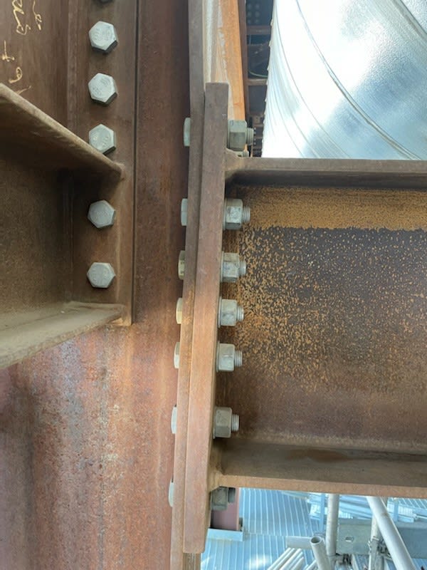
That looks like tension "prying" damage at the support. The difference in thickness between the end plate and the column flange is a big red flag.

The damage is already done and the column needs to be evaluated for adequacy. You'll need to provide more details if you want a proper remediation/retrofit strategy. For instance, what is the current state of construction/use of the building? Also, was this caused by construction loading, an errant crane/forklift, or something else? Being underdesigned for proper loads is one thing, avoiding site damage is quite another. Does it need to be brought back to it's former state or improved beyond the original capacity?
 
@DrZoidberWoop,

Thanks for your reply, This is a pipe rack structure the girder beam connected to the column was subjected to excess load due to hydro testing of the pipe which was not accounted for leading to the damage, the column itself is a major column carrying multiple levels of pipe rack above. It just needs to be brought back to former state.
 
I'm sorry, maybe someone else here has a clever solution, but "excessive unaccounted for loads" and "a major column carrying multiple levels of..." aren't descriptors that typically lead to cheap, quick, or painless fixes. It looks like you already have the floors above erected/pretensioned. If this is an indicator of a widespread potential problem on your project, a quick escalation and "stop-work" may be an unpopular, but necessary, measure. If concrete is poured within the vicinity of the column, your options for fixing the problem are drastically reduced.
 
@DrZoidberWoop,

I think I might have misexplained something here, this is a complete structure already built years ago. It just happened that it got loaded with the hydro testing of the pipe (by someone who is not aware that it should not) which lead to this damage. I wanted a fix for that local damage and this is not damage all around the structure it is localized only in this location.
 
I'm not sure that anything needs to be done here. I agree with Dr. Z's assessment that this is prying and not buckling. And, in the present state, I would say that the beam end plate is basically bracing the column flanges where you'd now be worried about buckling them potentially.

I wouldn't mind putting in column flange stiffeners above and below the plate bolt group for sport. That would require removing the transverse beam unfortunately.
 
I would probably refer to this as a CONNECTION failure in the column. You could call it "prying". But, I'd call it "column flange bending".

Does this affect the capacity of the column itself? I'm not sure that it does. My thoughts:

a) If this was due to hydro-testing, and the structure will never be hydrotested again, then maybe nothing needs to be done.
b) Preferably, I would reduce the demand on the column flange by turning it into a haunch connection. Essentially welding a WT cut from the same size beam, welding it to a connection plate of similar thickness. And, bolting them to the column. Increasing that distance by 50% should result in about a 33% reduction in the demand on the tension side.
 
Josh - I'm not following your repair concept.

Would the WT section & plate be welded to the sides of the column and span across the web?
 
Compare the buckling capacity of the column between brace points against the capacity in yield of the column at this point, accounting for the eccentricity, assuming the column is braced at this point. A structure not being to withstand the load from hydrotesting is pretty big red flag, I would probably try and sneak a partial depth stiffener there even if the structure is ok. Then again, we don't know the nature of the plant, although I am struggling to think of a situation where piping never needs hydrotesting and also carries fluid lighter than water.
 
Joel -

Sorry, I probably didn't explain myself too well. I grew up with these types of end plate moment connections for industrial structures. And, I started in 1996 when we had to use new procedures to reduce the demand on these connections in a post northridge regulatory environment. This type of haunched end plate connection was pretty common for us in the 1996 to 2002 time frame. Though this was for new construction, not retrofits.


The OP's current connection is merely a bolted end plate moment connection. So, we'd just be adding a haunch to the bottom. Similar to the following image (edited version of something from AISC's Design Guide 12- Modification of Existing Moment Connections).
WT_Haunch_from_Similar_to_AISC_DG_12_ehxkpb.png


The main differences from my image and the DG-12 is that original image was a directly welded connection, and I modified it to be a bolted end plate. Also, I identify the new items (bolts, extension to the existing end plate and the WT haunch) by coloring them red. We'd have a field weld between the WT web and the girder flange. We'd also have a shop weld between the WT flange / web at the new end plate. And, maybe another field weld between the extension of the plate and the existing plate.

Please forgive the crude drawing. I just screen captured the DG-12 image and modified it in paint. Note one of the topmost "bolt" shown in red is a mistake as it should be black for an existing bolt.
 
I like the haunch idea. If anything has been lost here, I suspect that it would be rigid joint connection stiffness during the early stages of lateral frame drift. The haunch would do a nice job of restoring that.
 
I'd be stiffening the column web too. If you're yielding the tension flanges the web will be copping a hammering too.
 
It's massive. It looks like a full moment connection into the unstiffened column. Load wise, it's not likely going anywhere. Can you just add a couple of small web stiffeners at the beam flange locations, just to accommodate any errant components from the reactions?

-----*****-----
So strange to see the singularity approaching while the entire planet is rapidly turning into a hellscape. -John Coates

-Dik
 
Thanks @joshplumSE , @KootK and @dik. I always see your replies to other threads and learned a lot from you all! I will go with the proposed haunch idea and add web stiffeners for peace of mind. I agree that it should have been designed with hydro testing in mind and that it surprised me it did not.
 
Don't forget to add backside stiffener between column flange at bottom (both sides), since you only made the beam stronger, the column bending capacity (against rotation or twist) is still inadequate.
 
Looks like there is also a vertical brace and beam framing into the weak axis of the column. That connection should be scrutinized as well, since no stiffeners were provided to deliver the brace force out to the column flanges.
 
Status
Not open for further replies.

Part and Inventory Search

Sponsor